Low-pressure saturated steam recycling equipment

A steam and low-pressure technology, which is applied in the direction of mechanical equipment, steam engine devices, machines/engines, etc., can solve the problems of affecting the operation of the process, reducing the fuel utilization rate, and the low heat utilization efficiency of the post-combustion steam superheating furnace.

Active Publication Date: 2012-07-11
思安新能源股份有限公司
View PDF9 Cites 8 Cited by
  • Summary
  • Abstract
  • Description
  • Claims
  • Application Information

AI Technical Summary

Problems solved by technology

[0004] However, the above two methods of using the by-product low-pressure saturated steam have their own shortcomings.
[0005] In the first way, the main disadvantages of superheating low-pressure saturated steam with supplementary combustion superheated steam furnace are: the use of supplementary combustion steam superheater increases the operation and maintenance of the entire system and additional fuel consumption, and due to supplementary combustion The heat utilization efficiency of the steam-fired superheating furnace is low, and the utilization rate of fuel will also be reduced
[0006] For the second method, the main disadvantage of adjusting low-pressure saturated steam of different pressure levels to the same level of pressure is that it is necessary to adjust each process in the system, which affects the operation of the process and reduces the pressure of low-pressure saturated steam with higher pressure. The energy grade, thereby reducing the cascade utilization of energy
In addition, this method will also prevent the low-pressure saturated steam of lower pressure from being recycled; on the other hand, it is necessary to modify the steam turbine and install a steam reheater between the steam turbine stages, which increases the production cost and manufacturing cost of the steam turbine. Complexity

Method used


Image

  • Low-pressure saturated steam recycling equipment
  • Low-pressure saturated steam recycling equipment

Examples


Embodiment Construction

[0024] In the following description, numerous specific details are given in order to provide a more thorough understanding of the present invention. It will be apparent, however, to one skilled in the art that the present invention may be practiced without one or more of these details. In other examples, some technical features known in the art are not described in order to avoid confusion with the present invention.

[0025] In order to provide a thorough understanding of the present invention, the detailed structure will be set forth in the following description. It is evident that the practice of the invention is not limited to specific details familiar to those skilled in the art. Preferred embodiments of the present invention are described in detail below, however, the present invention may have other embodiments besides these detailed descriptions.

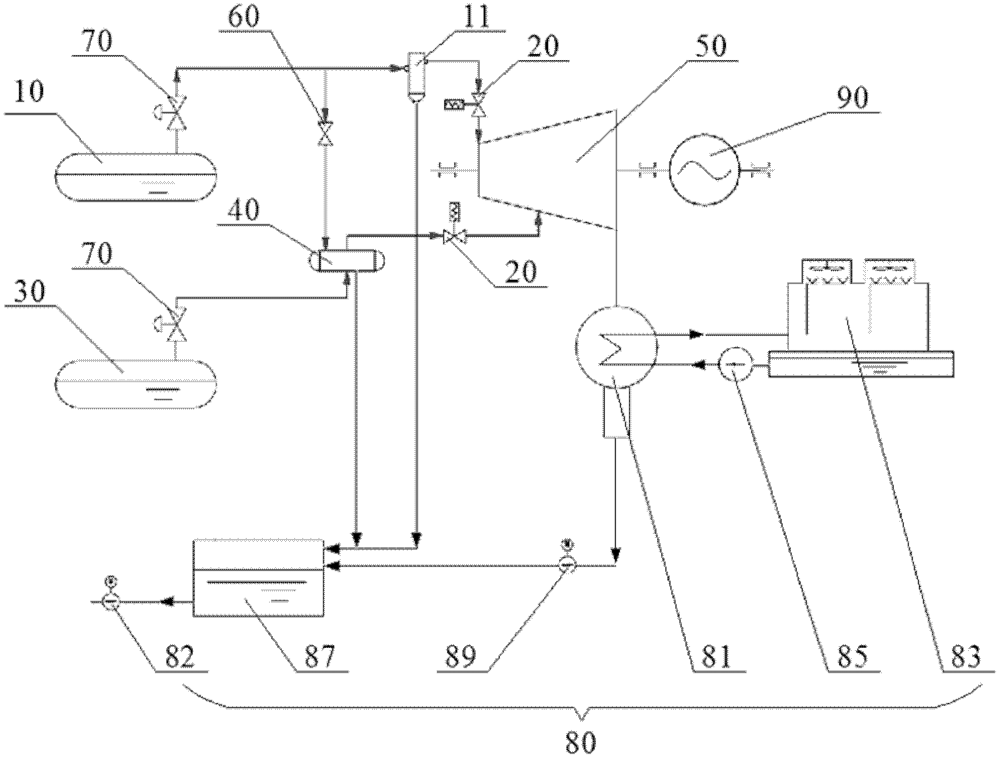
[0026] The invention discloses a low-pressure saturated steam recovery and utilization equipment, such as figure 1 As s...


PUM


Abstract

The invention discloses low-pressure saturated steam recycling equipment, which includes a heat accumulator, a steam drum and a steam turbine, wherein the heat accumulator is communicated with a high-pressure section of the steam turbine, so as to provide first low-pressure saturated steam for the high-pressure section of the steam turbine; the steam drum is communicated with a low-pressure section of the steam turbine, so as to provide second low-pressure saturated steam for the low-pressure section of the steam turbine; and the pressure and temperature of the first low-pressure saturated steam are both higher than those of the second low-pressure saturated steam. According to the low-pressure saturated steam recycling equipment disclosed by the invention, the first low-pressure saturated steam is conveyed to the high-pressure section of the steam turbine by the heat accumulator, the second low-pressure saturated steam is conveyed to the low-pressure section of the steam turbine by the steam drum, the first low-pressure saturated steam is mixed with the second low-pressure saturated steam after acting in the steam turbine for a period, and the first low-pressure saturated steam and the second low-pressure saturated steam continues acting after mixing, so that the continuous and stable running of the steam turbine is facilitated, and meanwhile the low-pressure saturated steam at different pressure and temperature levels are fully utilized.

Description

technical field [0001] The invention relates to the technical field of steam recovery and utilization, in particular to a low-pressure saturated steam recovery and utilization equipment. Background technique [0002] A large amount of low-pressure saturated steam is by-produced in the production process of steelmaking plants. The pressure of these by-produced low-pressure saturated steam is too low and has a high water content. It belongs to low-grade saturated steam resources and is usually used directly Thermal energy for heating or production of steam. However, due to the substantial reduction in the steam load of the steelworks in summer, the low-pressure saturated steam produced by this part has nowhere to be used and has to be discharged into the atmosphere, wasting the heat energy that can be used. With the promotion of my country's energy-saving and emission-reduction policies, steel mills have begun to pay attention to the recovery and utilization of this part of l...

Claims


Application Information

Patent Timeline
Patent Type & Authority Applications(China)
IPC IPC(8): F01K7/22F01K11/02F01D15/10
Inventor 肖衍党史晓云李晨飞韩涛李国强杜俊昭胡新
Owner 思安新能源股份有限公司
Why Eureka
Try Eureka