Gas turbine engine system, aircraft system, and method of operation

A technology of engine system and gas turbine, which is applied in the direction of gas turbine device, engine function, engine control, etc., and can solve problems such as engine stall

Active Publication Date: 2016-03-16
GE AVIATION SYST LLC
View PDF5 Cites 0 Cited by
  • Summary
  • Abstract
  • Description
  • Claims
  • Application Information

AI Technical Summary

Problems solved by technology

Because the engine stall problem is relatively new, there have been limited attempts to solve it

Method used


Image

  • Gas turbine engine system, aircraft system, and method of operation
  • Gas turbine engine system, aircraft system, and method of operation

Examples


Embodiment Construction

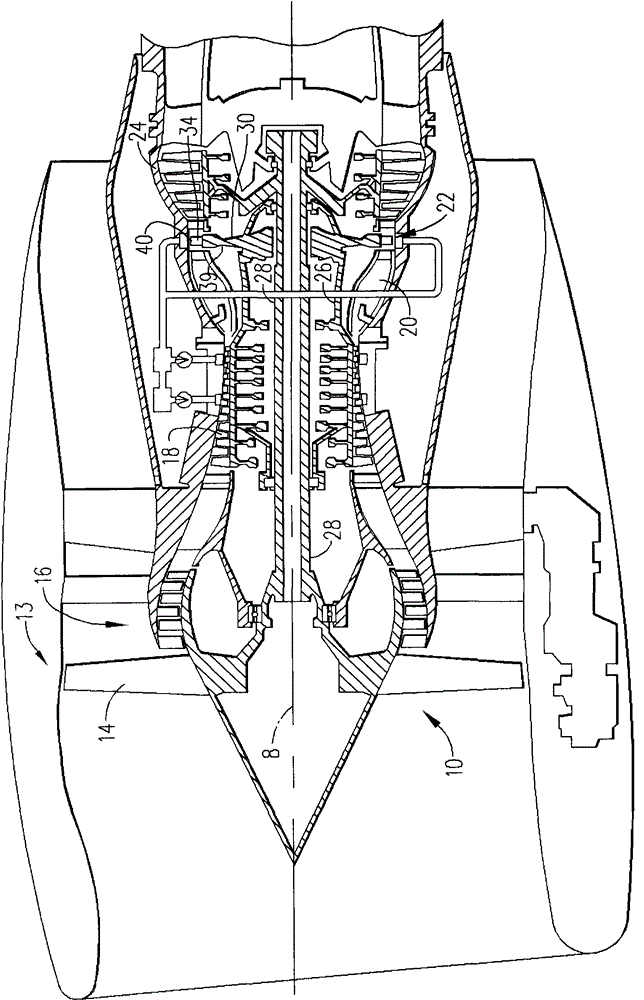
[0011] The following detailed description illustrates embodiments of the invention by way of example and not by way of limitation. This description clearly enables one skilled in the art to make and use the disclosure, which describes several embodiments, adaptations, variations, alternatives and utilizations of the disclosure, including what is presently believed to be the best mode of carrying out the disclosure. The present disclosure is described as applied to an exemplary embodiment, a system and method of providing power to an aircraft. However, it is contemplated that the present disclosure has broad application to electrical system architectures in industrial, commercial, and domestic applications.

[0012] As used herein, an element or step presented in the singular and preceded by the word "a" or "an" should be understood as not excluding plural elements or steps, unless such exclusion is explicitly stated. Furthermore, references to "one embodiment" of the present ...


PUM


Abstract

The present invention relates to methods and systems for powering vehicles. A method and system for operating an aircraft system is provided. A gas turbine engine system includes: a low pressure (LP) shaft; a high pressure (HP) shaft; a constant speed mechanical drive assembly having an input and an output mechanically coupled to the LP shaft and an output mechanically coupled to a constant frequency (CF) generator; and a Input and output accessory gearbox assemblies, the input mechanically coupled to the HP shaft and the output mechanically coupled to a variable frequency (VF) generator.

Description

technical field [0001] The field of the invention relates generally to aircraft electrical power generation and distribution systems, and more particularly to possible methods and systems for reducing high pressure turbine stall. Background technique [0002] At least some known aircraft are powered by two or more high bypass ratio turbofan engines. These engines include fans driven by low pressure spools that provide a substantial portion of the overall propulsion system thrust. The high voltage spool drives one or more compressors and additional thrust is generated by directing the exhaust products in a rearward direction. [0003] In addition to providing thrust to propel the aircraft and power the aircraft's hydraulic and pneumatic systems, the engines provide electrical power to many aircraft components, including environmental control systems, aircraft computers, hydraulic motor pumps, and / or other motors and electrical devices. One way to obtain electrical power fro...

Claims


Application Information

Patent Timeline
Patent Type & Authority Patents(China)
IPC IPC(8): F02C7/36B64G1/40
CPCF02C7/32F02C7/36F05D2220/76F05D2240/40F05D2260/85F05D2270/101
Inventor D·N·坦贾
Owner GE AVIATION SYST LLC
Why Eureka
Try Eureka