Heat exchanger

A technology of heat exchangers and plate heat exchangers, which is applied in the direction of heat exchange equipment, heat exchanger types, indirect heat exchangers, etc., can solve problems such as cracking of raised side walls and affecting the life of heat exchangers, and achieve increased performance, save welding materials, strong strength effect

Active Publication Date: 2012-07-11
DANFOSS AS
View PDF7 Cites 7 Cited by
  • Summary
  • Abstract
  • Description
  • Claims
  • Application Information

AI Technical Summary

Problems solved by technology

However, it has been found that these plates are prone to cracking at the raised side walls during operation of the heat exchanger
Obviously, this seriously and adversely affects the life of the heat exchanger

Method used


Image

  • Heat exchanger
  • Heat exchanger
  • Heat exchanger

Examples


Embodiment Construction

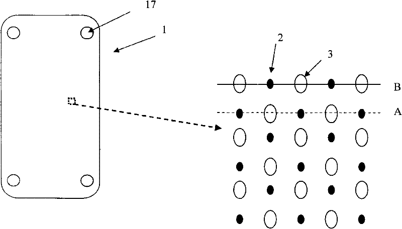
[0034] Figure 4 A plate heat exchanger (9) such as the exemplary embodiment shown in is a well known device for heat transfer between two different fluids. Plate heat exchangers (9) are used in many different applications, for example in the automotive industry, for cooling and heating buildings etc.

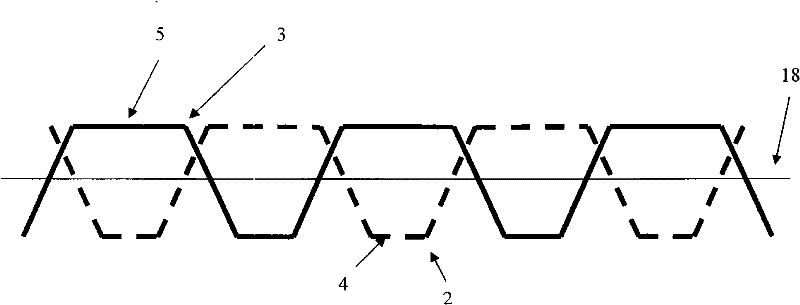
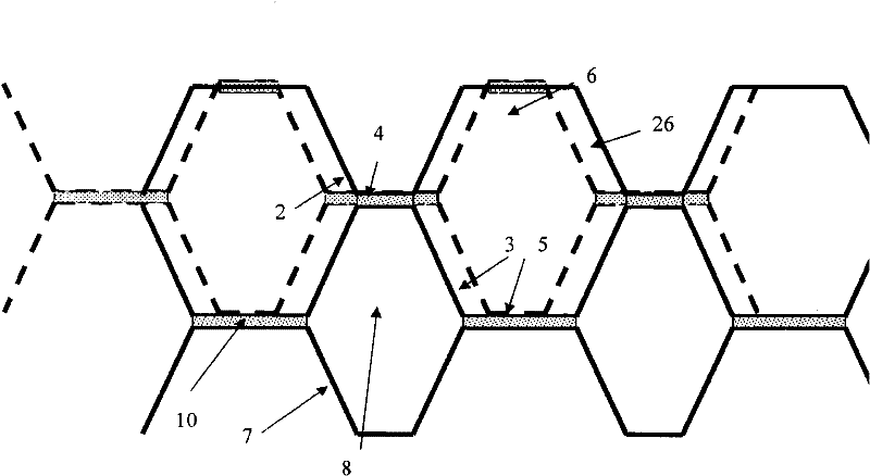
[0035] A plate heat exchanger (9) comprises a plurality of heat exchanger plates (1, 13) stacked on top of each other. Each heat exchanger plate (1, 13) is designed with an indentation pattern (2, 3, 14, 15), typically designed as protrusions and hollows and / or as ridges and recesses (the ridges and recesses being specifically combined with herringbone design). On the very top and the very bottom of the plate heat exchanger (9) flat metal plates (16) are provided for keeping the fluid inside the plate heat exchanger (9). Furthermore, connections (11, 12) for the inlet (11) and outlet (12) of the two fluids are provided.

[0036] A stack of heat exchanger plates (1, 13) is u...


PUM


Abstract

The invention relates to a plate heat exchanger (9), comprising a plurality of heat exchanger plates (1, 13), comprising at least one section showing indentations (2, 3, 14, 15), intended to be placed against corresponding indentations (2, 3, 14, 15) of a heat exchanger plate (1, 13) of a corresponding design. At least a first type of indentations (2, 14) and at least a second type of indentations (3, 15) is provided, wherein said first type of indentations (2, 14) and said second type of indentations (3, 15) are of a different design.

Description

technical field [0001] The present invention relates to a plate heat exchanger comprising at least one heat exchanger plate, preferably a plurality of heat exchanger plates, wherein at least one of said exchanger plates comprises At least one portion of the indentation is intended to be placed against a corresponding indentation of a correspondingly designed heat exchanger plate. Furthermore, the invention relates to a heat exchanger plate comprising at least one portion exhibiting an indentation intended to be placed against a corresponding indentation of a correspondingly designed heat exchanger plate. Background technique [0002] Heat exchangers of the plate heat exchanger type today are generally provided with plates having what is commonly called a herringbone pattern, which is a pattern with indentations made up of straight ridges and valleys. The ridges and valleys change their respective directions at the center, creating a chevron-like pattern. In a stacked heat ...

Claims


Application Information

Patent Timeline
Patent Type & Authority Applications(China)
IPC IPC(8): F28D9/00F28F3/04
CPCF28D9/005F28F2215/04F28F3/044
Inventor 拉尔斯·泊松
Owner DANFOSS AS
Why Eureka
Try Eureka