Depressurisation valve

a depressurisation valve and nuclear reactor technology, applied in the direction of valve operating means/release devices, nuclear elements, greenhouse gas reduction, etc., can solve the problems of affecting the operation of the valve, the failure of the nuclear reactor, and the increase in the heat produced by the radioactive decay within the fuel rod of the reactor to a point at which the reactor is damaged, so as to achieve the effect of reducing the fluid resistan

Active Publication Date: 2020-06-18
ROLLS-ROYCE SMR LTD
View PDF0 Cites 7 Cited by
  • Summary
  • Abstract
  • Description
  • Claims
  • Application Information

AI Technical Summary

Benefits of technology

[0007]According to a first aspect there is provided a depressurisation valve for a cooling circuit comprising a main valve having a piston and valve stem located in a main chamber, the main chamber being connected to a fluid supply via a pilot line with a secondary valve and a blowdown line, wherein fluid enters the main chamber via the pilot line, which has a lower fluid resistance than the blowdown line; and wherein in use the pressure of the fluid in the main chamber maintains the main valve in a closed position, and under extreme conditions fluid is prevented from entering the main chamber via a closure of the secondary valve on the pilot line and reduce the pressure from the valve, moving it to its open position.
[0008]The use of an opening valve as the passive valve allows for complete depressurisation of the core circuit. Furthermore, the valve can be applied in a number of configurations in which the valve can be positioned. Consequently, this valve acts as an improvement over the prior art and does not require the explosive charges required by the Squib.

Problems solved by technology

In emergency situations this is desirable as, in certain cases, power to the reactor may be disrupted or it may not be possible for operators to control the system manually in which case passive control systems allow the system to remain safe.
In the case of a pressurised water reactor one of the main safety concerns is a Loss of Coolant Accident (LOCA) event, in which the cooling water entering into the reactor is lost and would, if not rectified, lead to the failure of a nuclear reactor.
This is because without the coolant, the heat produced by the radioactive decay within the fuel rods of the reactor would increase to a point at which the reactor is damaged.
This could result in a serious nuclear incident.
One of the ways that this can occur is if the coolant boils, which can lead to the melt of the fuel clad and the release of the fission products.
As such, it is not suitable for the isolation of high pressure, high temperature water.
The Squib valve is equipped with an explosive charge that is used to open the valve; however, spurious operation of the squib valve could result in a major radiological hazard.
Consequently, the safety justification of the plant design is dependent upon a highly reliable Control and instrumentation (C&I) system to prevent spurious operation, and as such adds significant cost to the plant design.

Method used


Image

  • Depressurisation valve
  • Depressurisation valve
  • Depressurisation valve

Examples


second embodiment

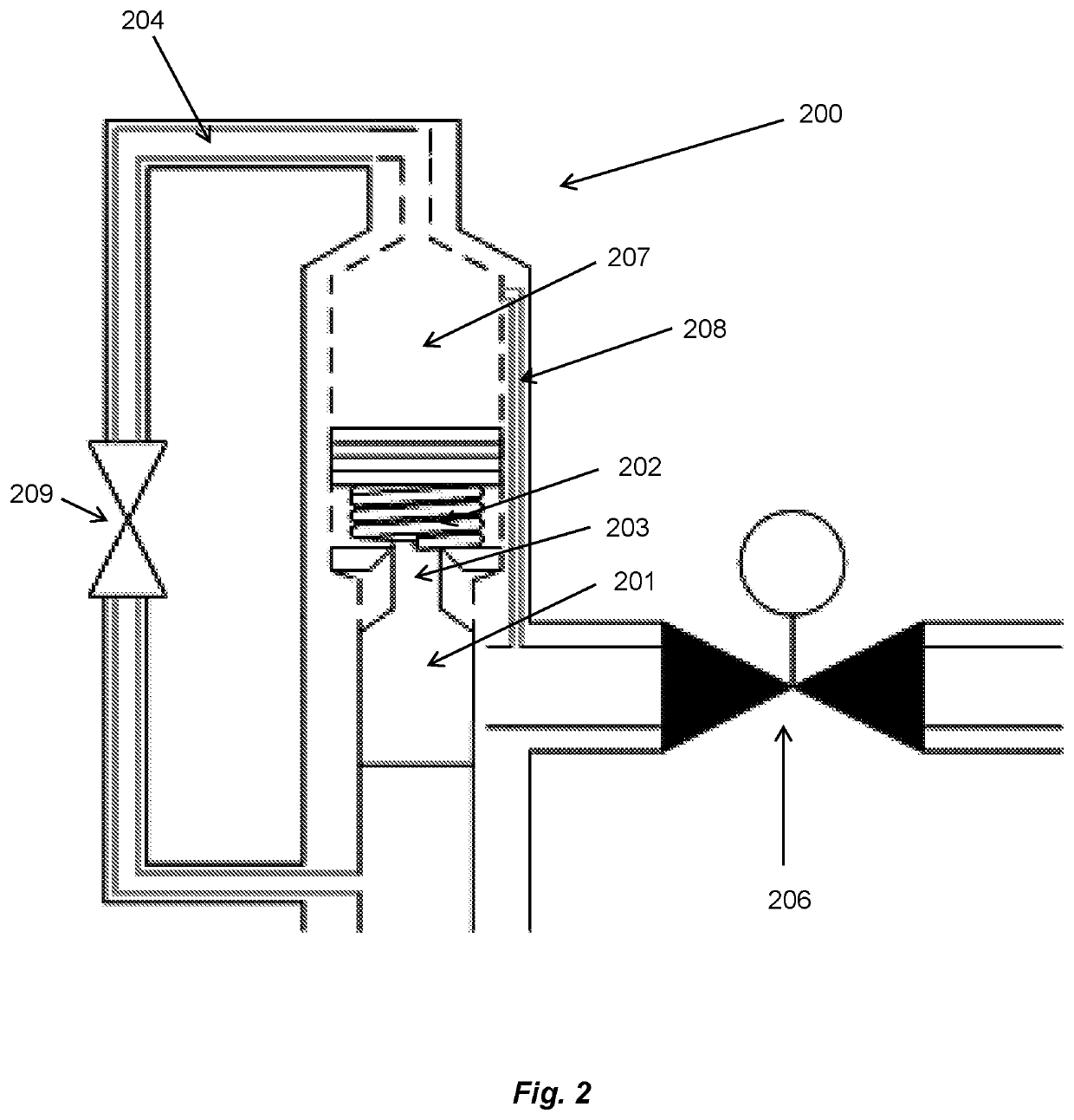
[0027]a PaD valve 200 removes the requirement for the pilot poppet valve; this embodiment is shown in FIG. 2. This configuration is similar in operation to that of the embodiment shown in FIG. 1. The main valve 201 is maintained in normal operation in a closed position within the circuit. It is maintained in this position by the fluid pressure from the coolant circuit passing through a pilot line 204 into a main chamber 207 at the back of a valve piston coupled to a valve stem 203. The fluid acts by applying a force on the valve piston and forces a compression spring 202 down, such that the main valve is maintained in the closed position. A blowdown line 208 is also provided to maintain fluid flow through the chamber. The blowdown line is narrower than the pilot line so that pressure in the main chamber is maintained. The pilot line is provided with secondary valve 209 for example this can be in the form of a magnovalve, which is thermally activated; this means that if the fluid tem...

third embodiment

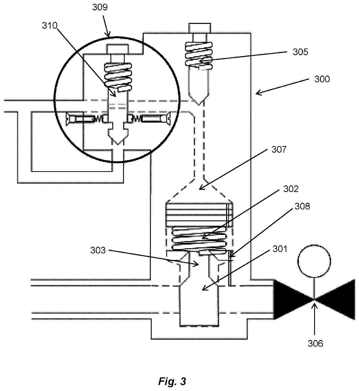
[0029]a PaD valve 300 of the present disclosure is presented in FIG. 3. In this example the secondary valve 309 incorporates a high pressure latching isolation valve 310 mounted on a pilot line 304; this acts as a pressure sensing line. This line works rather than on a thermal set point for closure of the valve, but rather it shuts down upon the detection of high pressures. The latching valve can be set to close at any suitable pressure that is outside of the normal operation of the cooling circuit. For example, the latching valve could be set to close at 16.5 MPa. The valve could also be set to close at pressures higher than this, for example at about 16.6, 16.7, 16.8, 16.9 17, 17.1, 17.2 17.3, 17.4, 17.5 MPa or higher. Or lower, for example at about 16.4 or 16.3, 16.2, 16.1 or 16 MPa. During normal operation of the reactor the typical pressure of the coolant will cause the fluid to flow along the dotted line. This pressure also retains the poppet valve in the open position. If how...


PUM


Abstract

A depressurisation valve for a cooling system comprising: a main chamber having a main valve, a pilot line having a secondary valve and a blowdown line; the main valve being located to seal a path of the coolant system of the nuclear reactor. The main chamber is connected to the cooling circuit via the pilot line allowing coolant to enter the main chamber, and the blowdown line allows coolant to escape from the main chamber, the pilot line having a lower fluid resistance than the blowdown line. The pressure of coolant in the main chamber maintains the main valve in a closed position, and under elevated temperature and / or pressure conditions fluid is prevented from entering the main chamber via a closure of the secondary valve on the pilot line and reduce the pressure from the valve, moving it to its open position.

Description

CROSS-REFERENCE TO RELATED APPLICATIONS[0001]This specification is based upon and claims the benefit of priority from United Kingdom patent application number GB 1820328.1 filed on Dec. 13, 2018, the entire contents of which are incorporated herein by reference.BACKGROUNDField of the Disclosure[0002]The present disclosure concerns a passive depressurisation valve for a nuclear reactor.Description of the Related Art[0003]Nuclear reactors are a desirable addition to a power grid as they present ideal base load stations. This is because they are considered a low carbon source of electricity and are not dependent upon variable weather conditions, which are limiting factors for other low carbon sources. These features allow them to be used as the backbone of a complete electricity network. One of the most common types of nuclear reactors used around the world is the pressurised water reactor (PWR) in which a primary circuit of pressurised water is used as the coolant, moderator and as we...

Claims


Application Information

Patent Timeline
Patent Type & Authority Applications(United States)
IPC IPC(8): G21C9/004F16K17/04F16K31/06
CPCF16K31/06F16K17/0486F16K17/048G21C9/004F16K17/22F16K17/34F16K17/38F16K17/383F16K31/383G21C15/18G21C13/02F16K31/084F16K31/002Y02E30/30Y02E30/00F16K17/10F16K17/003F16K15/1826Y10T137/7737
Inventor SHEARER, BRENTON DPALMER, JAMES CIRELAND, BENJAMIN J
Owner ROLLS-ROYCE SMR LTD
Why Eureka
Try Eureka