Recursion demodulation method for electrical tomography system

A technology of electrical tomography and demodulation method, which is applied in the field of recursive demodulation and can solve the problems of reducing flexibility and the like

Active Publication Date: 2012-07-11
BEIHANG UNIV
View PDF4 Cites 9 Cited by
  • Summary
  • Abstract
  • Description
  • Claims
  • Application Information

AI Technical Summary

Problems solved by technology

[0004] At present, the most commonly used digital phase-sensitive demodulation method is the orthogonal sequence demodulation method, but it requires tha

Method used


Image

  • Recursion demodulation method for electrical tomography system
  • Recursion demodulation method for electrical tomography system
  • Recursion demodulation method for electrical tomography system

Examples


Embodiment Construction

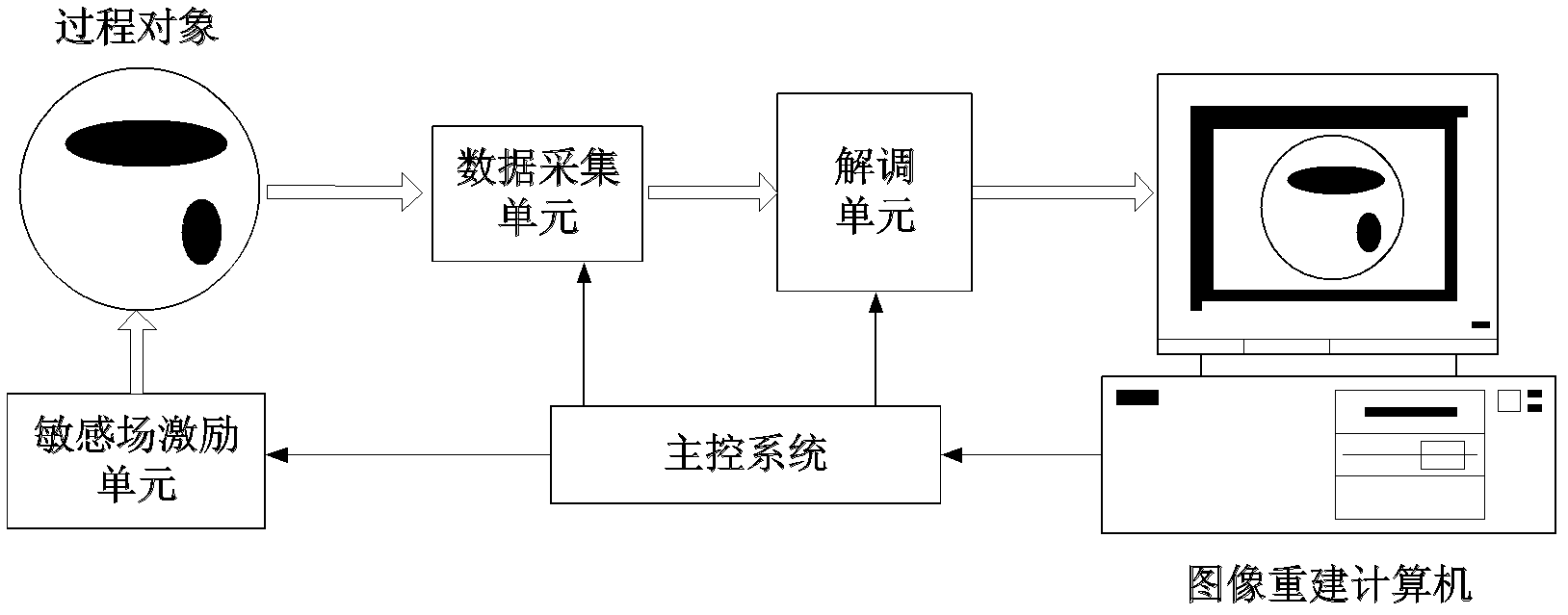
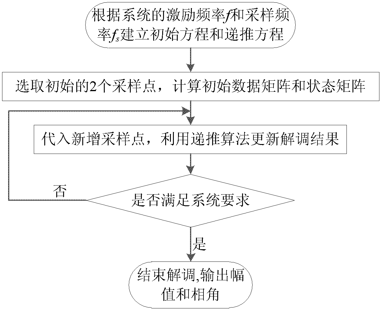
[0027] The present invention, that is, a recursive demodulation method for an electrical tomography system, comprises the following steps:

[0028] Step 1. According to the excitation frequency f and sampling frequency f of the system s Create a recursive demodulation equation.

[0029] Suppose the representation of the measurement signal is:

[0030] x k =Acos(2πkf / f s +θ) (1)

[0031] Among them, k is the number of sampling points, A is the amplitude of the measurement signal, and θ is the phase difference between the measurement signal and the excitation signal. According to Euler's formula, x k Can be expressed as:

[0032] x k = A 2 e - jθ · e - 2 πkf / f s + ...


PUM


Abstract

The invention relates to a recursion demodulation method for an electrical tomography system, which is characterized by comprising the following steps: (1) establishing an initial equation and a recursion equation according to an excitation frequency f and a sampling frequency f s of a system; (2) taking a zero phase moment of an excitation signal as an initial moment, and calculating initial values of a data matrix B and a state matrix P based on an initial equation in step (1) according to two sampling point data of a measurement signal immediately after the initial moment; (3) substituting the initial values of the data matrix B and the state matrix P as well as newly added sampling point data into the recursion equation in step (1) so as to update B and P; and (4) judging whether a demodulation result meets the accuracy requirement of the system or not, if not, returning to step (3), and if so, finishing demodulation and outputting the amplitude and phase data of the measurement signal. The recursion demodulation method only needs at least two sampling point data, and can improve demodulation accuracy and anti-noise ability by adding sampling points.

Description

technical field [0001] The invention relates to a recursive demodulation method for an electrical tomography system, belonging to the field of distribution parameter measurement. Background technique [0002] The working principle of electrical tomography is based on the different electrical properties (conductivity / dielectric constant / complex admittance) of different media, by obtaining the measurement data of the boundary of the sensitive area and using an appropriate image reconstruction algorithm to invert the inversion of the sensitive area. The distribution of electrical parameters, and then obtain the distribution of the medium in the region. A typical structure of an electrical tomography system is as follows: figure 1 shown. At present, in order to obtain a better measurement signal-to-noise ratio, linearity and resolution, electrical tomography systems mostly use sinusoidal signals as excitation sources, and phase-sensitive demodulation methods are generally used...

Claims


Application Information

Patent Timeline
IPC IPC(8): G01R27/26G01R27/04
Inventor 徐立军周海力曹章曾轶
Owner BEIHANG UNIV
Why Eureka
Try Eureka