
Collimator for a radiation detector and method for manufacturing such a collimator as well as method for manufacturing a radiation detector

A ray detector and collimator technology, which is applied in radiation measurement, X/γ/cosmic radiation measurement, instruments, etc., can solve the problems of ray converter shadow, signal-to-noise ratio reduction, incorrectness, etc., and achieve simplified positioning Effect

Active Publication Date: 2012-07-11
SIEMENS HEALTHCARE GMBH
View PDF9 Cites 9 Cited by
  • Summary
  • Abstract
  • Description
  • Claims
  • Application Information

AI Technical Summary

Problems solved by technology

[0004] Slight inclinations or incorrect positioning of the collimator relative to the radiation detector can lead to shadowing of the active area of ​​the radiation converter and thus lead to incorrect or reduced achievable signal-to-noise ratios
A particular challenge when constructing the radiation detector is therefore to align the collimator in a very precise manner relative to the radiation converter

Method used


Image

  • Collimator for a radiation detector and method for manufacturing such a collimator as well as method for manufacturing a radiation detector
  • Collimator for a radiation detector and method for manufacturing such a collimator as well as method for manufacturing a radiation detector
  • Collimator for a radiation detector and method for manufacturing such a collimator as well as method for manufacturing a radiation detector

Examples


Embodiment Construction

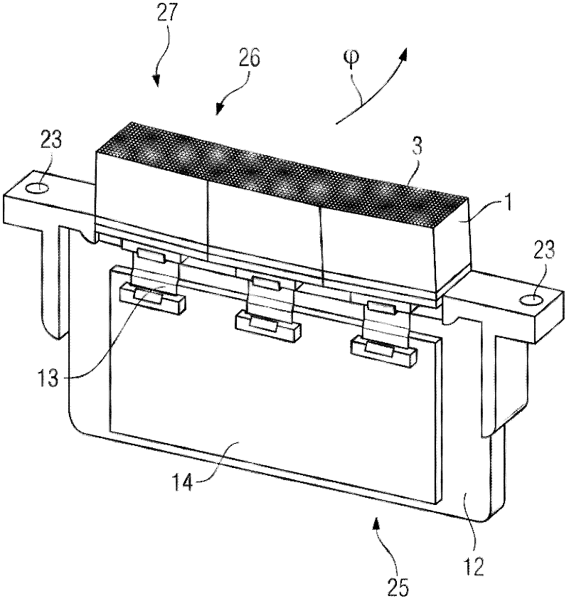
[0033] Components having the same effect in the figures are identified with the same reference numerals. For the sake of clarity, elements that are repeated in one figure, such as the detector element 22 , are each designated with a reference number for only one element. The illustrations in the figures are schematic and not necessarily to scale, wherein dimensions may vary between figures.

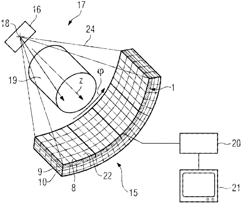
[0034] figure 1 A computed tomography system 17 is shown, which comprises a radiation source 16 in the form of an x-ray tube, from which a focal point 18 emits an x-ray fan 24 . The x-ray fan 24 passes through the object 19 to be examined or the patient and strikes the radiation detector 15 , here an x-ray detector.

[0035] The x-ray tube 16 and the x-ray detector 15 are arranged opposite each other on a gantry (not shown here) of a computed tomography system 17 , which can be placed on direction around the system axis Z (=patient axis). that is The direction denotes the circumfer...


PUM


Abstract

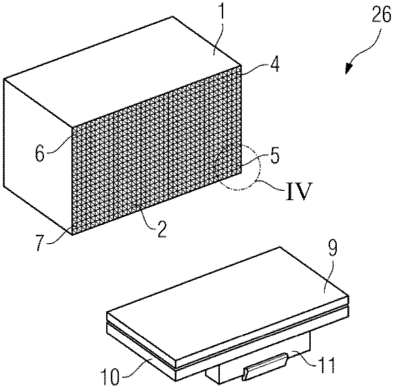
The present invention relates to a collimator (1) for a radiation detector (15) including at least three spacing elements (4, 5, 6, 7) arranged on a radiation exit face (2) of the collimator (1). he spacing elements are to mount the collimator in a stable manner with respect to a radiation converter (9, 10) of the radiation detector (15). At least three of the spacing elements (4, 5, 6, 7) enable a very precise and stable alignment of the collimator (1) in respect of the radiation converter despite manufacturing-related curves or unevennesses in the radiation exit face (2) and / or the mounting surface on the part of the radiation converter (9, 10). The invention also relates to a manufacturing method for such a collimator, as well as a method for manufacturing a radiation detector (15).

Description

technical field [0001] The invention relates to a collimator for a radiation detector, a method for producing such a collimator, and a method for producing a radiation detector with a collimator. Background technique [0002] Scattered radiation is mainly produced by the interaction of the primary radiation emitted from the focal point of the radiation source with the object to be examined. As a result of this interaction, the scattered radiation hitting the radiation converter of the radiation detector from a different spatial direction than the primary radiation leads to artifacts in the reconstructed image. [0003] In order to reduce the detected scattered radiation component in the detector signal, the radiation converter is therefore connected upstream of the collimator. Such a collimator has absorbing elements arranged in one or two dimensions, the absorbing surface of which is radially aligned in the shape of a fan to the focus of the radiation source, so that only ...

Claims


Application Information

Patent Timeline
IPC IPC(8): G01T7/00G01T1/161
CPCG01T1/1648Y10T156/10
Inventor A.弗罗因德C.波翰G.肖帕S.沃斯J.雷治
Owner SIEMENS HEALTHCARE GMBH
Learn More