Maximum power point tracking method under partial shade condition of photovoltaic system

A maximum power point, photovoltaic system technology, applied in photovoltaic power generation, control/regulation systems, instruments, etc., can solve problems such as system efficiency decline, inability to track the maximum power point, etc., to speed up the search speed and avoid falling into local extremes , the effect of speeding up the search speed and accuracy

Inactive Publication Date: 2012-07-11
AUTOMATION RES & DESIGN INST OF METALLURGICAL IND
View PDF5 Cites 18 Cited by
  • Summary
  • Abstract
  • Description
  • Claims
  • Application Information

AI Technical Summary

Problems solved by technology

[0009] The purpose of the present invention is to provide a maximum power point tracking method under partial shading conditions of a photovoltaic system, which solves the problem that the battery panels in

Method used


Image

  • Maximum power point tracking method under partial shade condition of photovoltaic system
  • Maximum power point tracking method under partial shade condition of photovoltaic system

Examples


Embodiment Construction

[0021] Taking a 30kW photovoltaic array as an example, the open circuit voltage is 820V, the short circuit current is 49.3A, and the shading conditions are 1000W / m2 and 500W / m2 respectively.

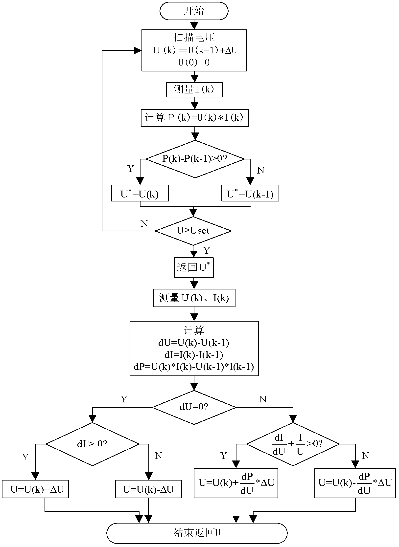
[0022] The concrete operating steps of the inventive method are:

[0023] 1. Initially provide the array with a step size of ΔU=5V and a scanning range of 0.1V-U set =800V scanning voltage, then measure the output current I(k) of the photovoltaic array;

[0024] 2. Calculate the output power P(k)=U(k)*I(k), by comparing with the last output power P(k-1)=U(k-1)*I(k-1), Assign the scanning voltage value at the place with higher output power to U*; after scanning, U*=695V;

[0025] 3. Take the returned U*=695V as the initial value of the incremental conductance method, and use ΔU=0.5V as the step size. Measure the output current I(k) of the panel, calculate dU=U(k)-U(k-1), dI=I(k)-I(k-1), dP=U(k)*I(k )-U(k-1)*I(k-1);

[0026] 4. If dU is 0, judge the positive or negative of dI. If dI i...


PUM


Abstract

The invention discloses a maximum power point tracking method under a partial shade condition of a photovoltaic system, and belongs to the technical field of a photovoltaic power generation system. The maximum power point tracking method comprises the following steps of: searching a point close to a peak value of the maximum power point by using voltage scanning; and finally determining the position of the maximum power point using a variable step incremental conductance method by taking a voltage value of the point as an initial value of the incremental conductance method. According to the method, the problem of reduced system efficiency caused by incapability of tracking the maximum power point in the case that a battery panel in the photovoltaic system is under a shade condition is solved. The method has the advantages of simple structure and capability of effectively avoiding local extremum produced when the photovoltaic system gets into local shade.

Description

technical field [0001] The invention belongs to the technical field of photovoltaic power generation systems, and in particular provides a method for tracking a maximum power point of a photovoltaic system under partial shading conditions. Background technique [0002] Most of the existing maximum power point tracking methods are based on the fact that the photovoltaic cell output P-V characteristic (power-voltage characteristic) has a peak value. The most commonly used methods of constant voltage, perturbation and observation, and conductance increment will be completely useless under the condition of multiple peaks caused by shading. [0003] Disadvantages of the constant voltage method: the maximum power point voltage is fixed at the beginning, and cannot be tracked when the peak position changes. [0004] Disadvantages of the perturbation and observation method: change the perturbation direction based on the comparison result of the output power. Since the perturbation ...

Claims


Application Information

Patent Timeline
IPC IPC(8): G05F1/67
CPCY02E10/58Y02E10/56
Inventor 张渊明孙彦广张云贵
Owner AUTOMATION RES & DESIGN INST OF METALLURGICAL IND
Why Eureka
Try Eureka