Demodulator circuit of electronic tag of RFID (radio frequency identification) system

A technology of electronic tags and demodulators, which is applied to instruments, record carriers used by machines, computer components, etc., and can solve problems such as difficulties and complex designs

Active Publication Date: 2012-07-11
SHANGHAI HUAHONG GRACE SEMICON MFG CORP
View PDF3 Cites 16 Cited by
  • Summary
  • Abstract
  • Description
  • Claims
  • Application Information

AI Technical Summary

Problems solved by technology

But for the 10% ASK modulation signal of Type B type, because the difference between the high and low amplitudes is relatively small,

Method used


Image

  • Demodulator circuit of electronic tag of RFID (radio frequency identification) system
  • Demodulator circuit of electronic tag of RFID (radio frequency identification) system
  • Demodulator circuit of electronic tag of RFID (radio frequency identification) system

Examples


Embodiment Construction

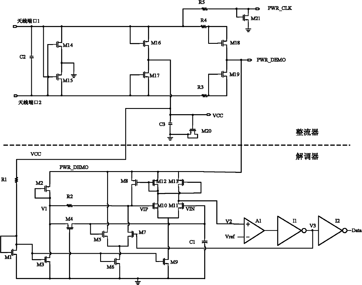
[0038] see figure 1 , which is a specific embodiment of the demodulator circuit of the electronic tag of the RFID system of the present invention. The part above the dotted line in this embodiment is a rectifier circuit, and the part below the dotted line is a demodulator circuit. Both the rectifier and the demodulator are electronic label components in the analog front-end circuit.

[0039] The demodulator circuit includes 13 MOS transistors M1-M13, 2 resistors R1 and R2, 1 capacitor C1, 1 operational amplifier A1 and 2 inverters I1 and I2. Its specific circuit structure is as follows:

[0040] The base of the first MOS transistor M1 is connected to the collector, and connected to the regulated working voltage VCC through the first resistor R1; the emitter of the first MOS transistor M1 is grounded.

[0041] The base of the second MOS transistor M2 is connected to the collector, and the emitter is connected to the power supply voltage PWR_DEMO with the modulation signal rem...


PUM


Abstract

The invention discloses a demodulator circuit of an electronic tag of an RFID system. Different from the conventional design, the demodulator circuit acquires a demodulation signal directly from a power supply PWR_DEMO outputted by a rectifier, and achieves demodulation, amplification, shaping and outputting of a weak signal by using an asymmetric circuit design. Specifically, the demodulator circuit conducts demodulation by using envelope detection method, and adopts a secondary comparison circuit. The demodulator circuit of the electronic tag of the RFID system provided by the invention can achieve demodulation of 10% ASK (amplitude shift keying) modulated signals, which are defined as type B according to the standard of ISO/IEC (International Organization for Standardization/International Electrotechnical Commission) 14443-3.

Description

technical field [0001] The invention relates to a radio frequency analog front-end circuit of an electronic tag of an RFID system, in particular to a demodulator circuit in the radio frequency analog front-end circuit. Background technique [0002] RFID (radio frequency identification, radio frequency identification) is a non-contact automatic identification technology. An RFID system includes at least two parts: a transponder and an interrogator. The transponder is also called the electronic tag (tag). An interrogator, also known as a reader, is a device for reading and / or writing electronic tags. [0003] The electronic tag generally includes an antenna, a radio frequency analog front-end circuit, a digital baseband circuit, and a storage unit (such as EEPROM, etc.). Conventional RF analog front-end circuits mainly include: [0004] Rectifier: converts the AC voltage coupled from the antenna into a DC voltage. It is used for the RF analog front-end circuit and the ent...

Claims


Application Information

Patent Timeline
IPC IPC(8): G06K19/07
Inventor 朱红卫彭敏
Owner SHANGHAI HUAHONG GRACE SEMICON MFG CORP
Why Eureka
Try Eureka