Modularized counting machine

A counting machine, modular technology, applied in the direction of handling coins or valuable banknotes, instruments, etc., can solve the problems of not meeting the requirements of banknote counting and authenticating, complicated installation, difficult maintenance, etc., to improve the adaptability and detection ability of the machine, The effect of improving production efficiency, facilitating maintenance and after-sales service work

Active Publication Date: 2012-07-11
JULONG
View PDF6 Cites 11 Cited by
  • Summary
  • Abstract
  • Description
  • Claims
  • Application Information

AI Technical Summary

Problems solved by technology

[0002] At present, the banknote counting equipment most used by banks and related financial institutions in my country is the banknote counting machine. The function of the banknote counter is very simple. It can only count and do simple counterfeit work, which is far from meeting the increasingly complex banknote counting and counterfeiting requirements.
Banknote counters are unable to meet the requirements of banknotes for sorting new and old, authenticity, damage, folded corners and adhesive tape banknotes, as well as the counterfeit identification needs of counterfeit coins and patchwork coins that appear in the market at present. Can only be done with a more complex sorting machine
In order to meet the above requirements, the current banknote sorting machine has added a lot of detection devices, which makes the machine body bulky, noisy, complicated to install, and difficult to maintain.
The Chinese invention patent "A Two-Channel Banknote Automatic Sorting Machine" (Patent No.: 200510047213.0) is relatively small in the sorting machine market, but due to the more complicated banknote detection device and the corresponding transmission for realizing counterfeiting And supporting parts, the whole machine still has the above-mentioned problems of bulky body, loud noise, complicated installation and difficult maintenance

Method used


Image

  • Modularized counting machine
  • Modularized counting machine
  • Modularized counting machine

Examples


Embodiment Construction

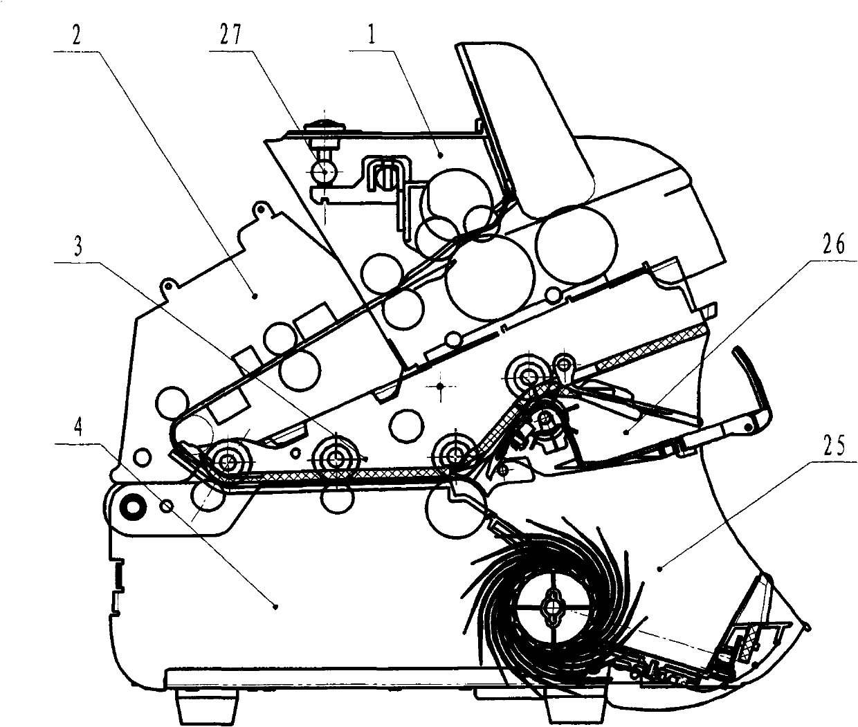
[0038] The whole machine structure of the modularized counting machine of the present invention is composed of four main modules: a banknote feeding module, a detection module, a middle warehouse module and a bottom warehouse module. The components are fastened together.

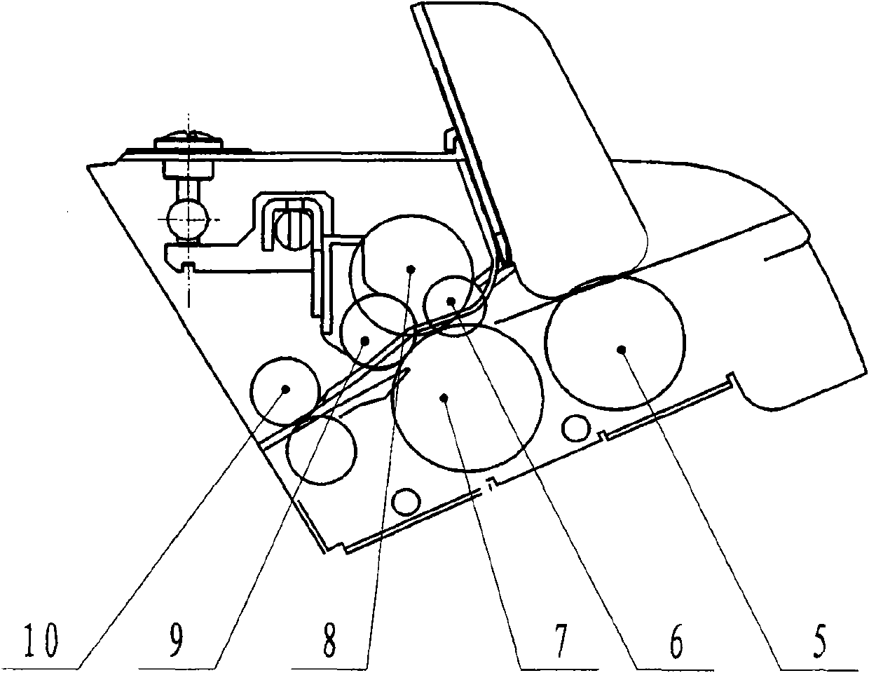
[0039] The banknote feeding module is mainly composed of a banknote feeding wheel, a banknote twisting wheel, a resistance wheel, a pressing wheel before twisting banknotes, and a pressing wheel after twisting banknotes, and completes the function of separating and entering banknotes.

[0040] In the banknote feeding module, the upper part of the banknote feeding module composed of a resistance wheel, a pressure wheel before twisting banknotes, and a pressure wheel after twisting banknotes can rotate around the first central axis.

[0041] A first transmission element is installed in the banknote feeding module, and the first transmission element may be a banknote thickness measuring device.

[0042] The de...


PUM


Abstract

The invention relates to a modularized counting machine which comprises a bank note feeding module, a detecting module, a middle cabin module and a bottom cabin module, wherein the detecting module is continuously connected with the rear part of the bank note feeding module; the middle cabin module is continuously connected with the rear part of the detecting module; the bottom cabin module serves as a supporter of the modularized counting machine; a connected bank note channel for conveying the bank note is arranged among the bank note feeding module, the detecting module, the middle cabin module and the bottom cabin module; the bank note feeding module, the detecting module and the middle cabin module are fixedly connected with each other through a first connecting element and a second connecting element; a third central shaft is arranged at one end of the middle cabin module; the middle cabin module is hinged with the bottom cabin module through the third central shaft; and a main motor used for driving the modularized counting machine to run is mounted on the bottom cabin module. The modularized counting machine provided by the invention is simple in structure and is easily assembled and maintained.

Description

technical field [0001] The invention relates to a financial currency detection and counting machine tool, in particular to a modularized counting machine. Background technique [0002] At present, the banknote counting equipment most used by banks and related financial institutions in my country is the banknote counting machine. The function of the banknote counter is very simple. It can only count and do simple counterfeit work, which is far from meeting the increasingly complex banknote counting and counterfeiting requirements. . Banknote counters cannot meet the requirements for sorting old and new banknotes, authenticity, damage, folded corners and adhesive tape banknotes, as well as the counterfeit identification needs of counterfeit coins and patchwork coins that appear in the market. It can only be done with a more complex sorting machine. However, in order to meet the above requirements, the current banknote sorting machine has added a lot of detection devices, whic...

Claims


Application Information

Patent Timeline
Patent Type & Authority Applications(China)
IPC IPC(8): G07D13/00
Inventor 柳长庆柳永诠牛作琴张丽君袁秀清孟凡刚吴庆洪柳伟生洪振胜王凌志于淼
Owner JULONG
Why Eureka
Try Eureka