Microwave parabolic antenna with long-focus feedback super-high performance

A parabolic antenna, ultra-high-performance technology, applied in antennas, antenna coupling, electrical components and other directions, can solve the problems of poor circular symmetry of the antenna pattern, difficult to match the antenna and feeder well, and difficult to use large-diameter antennas. The effect of shortening the supply cycle, saving manpower and material resources, and improving the efficiency of the antenna

Active Publication Date: 2012-07-11
XIAN PUTIAN ANTENNA
View PDF6 Cites 10 Cited by
  • Summary
  • Abstract
  • Description
  • Claims
  • Application Information

AI Technical Summary

Problems solved by technology

The disadvantages are: since the radiator is located in the electric field of the parabolic reflector, the reflector has a large reaction to the radiator, and it is difficult to get a good match between the antenna and the feeder; the back radiation is large; the degree of protection is poor; the manufacturing accuracy is high
However, due to its complex processing and molding, high cost, poor consistency, and the circular symmetry of the antenna pattern is not good due to the shielding of the curved waveguide, which in turn affects other electrical properties of the antenna
[0004] The short-focus microwave parabolic antenna with sputtering plate direct waveguide feed source developed by the applicant in the early stage has solved the above-mentioned problems of the traditional curved waveguide feed source microwave antenna. However, with the continuous development of communication technology, it is necessary to use larger A microwave antenna with higher aperture, higher gain, and better electrical performance; while the short-focus microwave parabolic antenna with a splash plate direct-guided feed is only suitable for small-aperture antennas, and it is difficult to play the required role in large-aperture antennas

Method used


Image

  • Microwave parabolic antenna with long-focus feedback super-high performance
  • Microwave parabolic antenna with long-focus feedback super-high performance
  • Microwave parabolic antenna with long-focus feedback super-high performance

Examples


Embodiment Construction

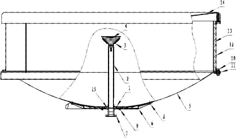
[0036] see figure 1 with figure 2 , this embodiment provides a telephoto rear feed ultra-high performance parabolic antenna, including:

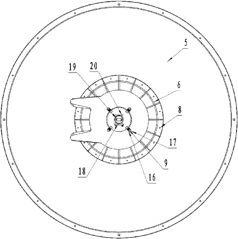
[0037] A standard rotating parabolic main reflector 5 formed by stamping or spinning;

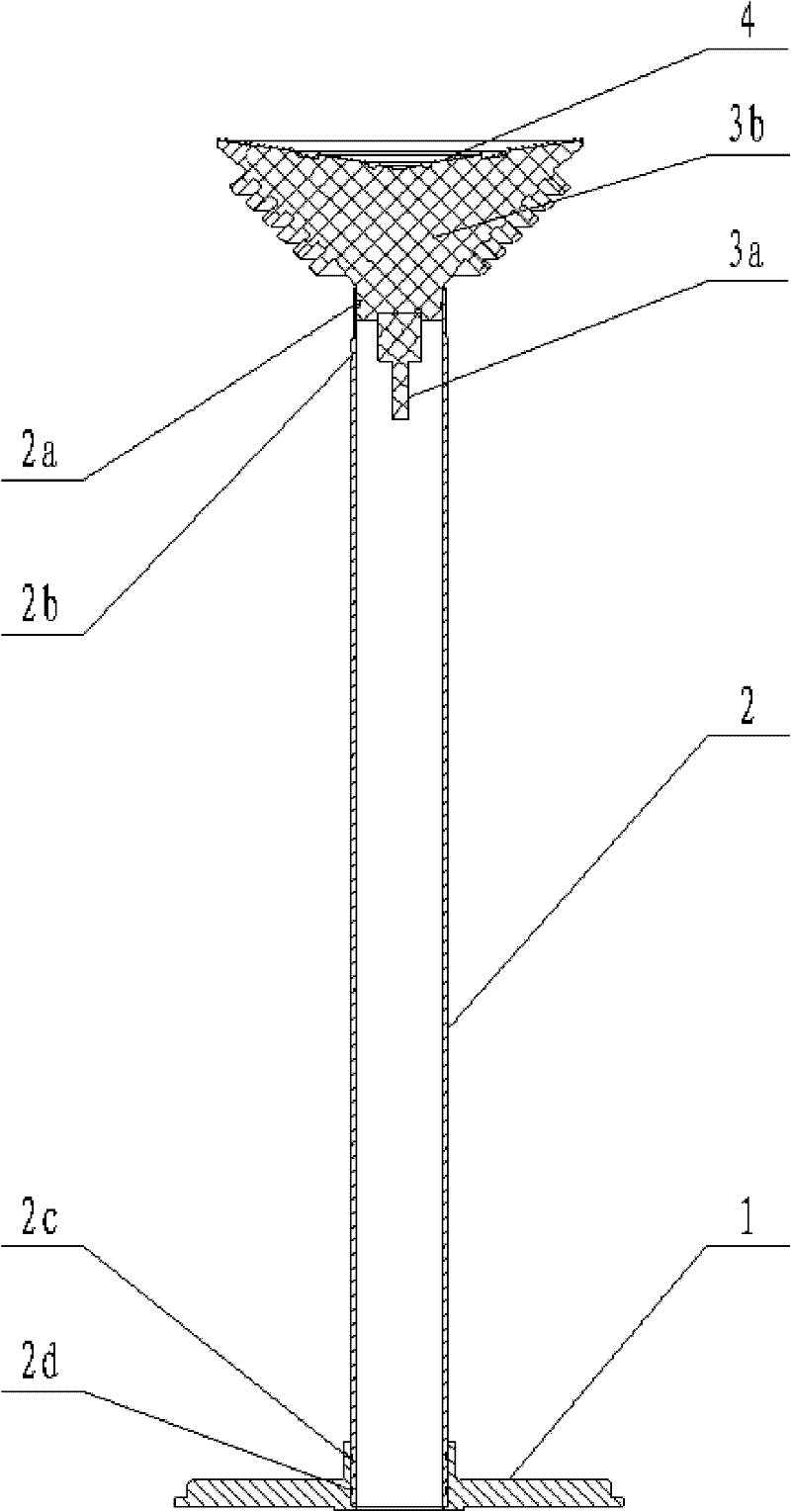
[0038] A circular waveguide 2 fed along the axial direction of the main reflector (5);

[0039] A shaped rotationally symmetrical dielectric splash plate 3, the dielectric splash plate 3 is located above the circular waveguide 2;

[0040] A sub-reflector 4 formed by metal coating on the bottom surface of the dielectric scatter plate 3;

[0041] A feed connection plate 1 connecting the circular waveguide 2 and the main reflector 5 together;

[0042] A metal shielding ring 12 connected to the outer edge of the main reflector 5, the inner surface of the metal shielding ring 12 is pasted with an absorbing material 13 for improving electromagnetic radiation performance;

[0043] A radome 14 covering the outside of the metal shielding ring 12 .

[0044] ...


PUM


Abstract

The invention discloses a microwave parabolic antenna with long-focus feedback and super-high performance. The microwave parabolic antenna comprises a standard rotary parabolic main reflector, a round waveguide pipe, a dielectric sputtering plate, an auxiliary reflector, a feed source connecting disc, a metal shielding ring and other assembling and mounting parts, wherein the standard rotary parabolic main reflector is formed through punching or spinning; the round waveguide pipe feeds electricity along the axial line direction of the main reflector; the dielectric sputtering plate is shaped and rotationally symmetric; the auxiliary reflector is formed by metal-plating on the bottom surface of a dielectric sputtering plate; the feed source connecting disc is used for connecting the round waveguide pipe with the main reflector together; the metal shielding ring is connected to the outer edge of the main reflector; and the round waveguide pipe, the feed source connecting disc and the dielectric sputtering plate are positioned on the axial line of the main reflector and are bonded and assembled together to form a core of the whole antenna. The microwave parabolic antenna with long-focus feedback and super-high performance is excellent in performance, lower in cost, attractive in appearance, high in practicability and high in consistency, can be used in a microwave circuit concentrating place, is easy to machine and is more suitable for mass production.

Description

technical field [0001] The invention relates to a microwave antenna, in particular to a telephoto rear feed ultra-high performance microwave parabolic antenna. Background technique [0002] The parabolic antenna is a directional microwave antenna, which consists of a parabolic reflector and a radiator. The radiator is installed on the focal point or focal axis of the parabolic reflector. The electromagnetic wave emitted by the radiator is reflected by the parabola to form a highly directional beam. The parabolic antenna has the advantages of simple structure, strong directivity, and wide operating frequency band. The disadvantages are: since the radiator is located in the electric field of the parabolic reflector, the reflector has a large reaction to the radiator, and it is difficult to get a good match between the antenna and the feeder; the back radiation is large; the protection degree is poor; the manufacturing precision is high. This antenna is widely used in microwa...

Claims


Application Information

Patent Timeline
Patent Type & Authority Applications(China)
IPC IPC(8): H01Q19/19H01Q1/52H01Q17/00
Inventor 鱼军浪张铁军郭勇韦大卫吕磊梁娟刘飞杨英
Owner XIAN PUTIAN ANTENNA
Why Eureka
Try Eureka