
Power conversion system based on energy storage of lithium battery and control method thereof

A power conversion system, lithium battery technology, applied in the output power conversion device, the conversion of AC power input to DC power output, electrical components and other directions, can solve the problem of neglecting the protection of the energy storage battery system and the poor effect of grid-connected harmonic filtering , the power conversion system equipment is complex and other problems, to achieve the effect of saving inductor core materials, avoiding overcharge or overdischarge state, and improving power utilization

Active Publication Date: 2012-07-11
CHINA ELECTRIC POWER RES INST
View PDF4 Cites 11 Cited by
  • Summary
  • Abstract
  • Description
  • Claims
  • Application Information

AI Technical Summary

Problems solved by technology

[0005] The purpose of the present invention is to overcome the shortcomings of the existing power conversion system such as complex equipment, low bidirectional power conversion efficiency, neglect of energy storage battery system protection, poor grid-connected harmonic filtering effect, lack of dead zone compensation, etc., and propose a new Power conversion system with hardware structure and its control method

Method used


Image

  • Power conversion system based on energy storage of lithium battery and control method thereof
  • Power conversion system based on energy storage of lithium battery and control method thereof
  • Power conversion system based on energy storage of lithium battery and control method thereof

Examples


Embodiment Construction

[0026] The present invention will be further described below with reference to the drawings and specific embodiments.

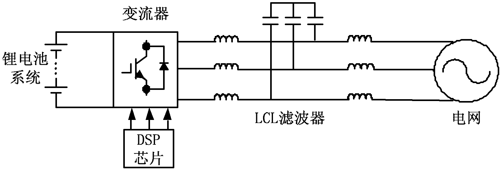
[0027] figure 1 It is the topological structure diagram of the power conversion system for the lithium battery system. The structure adopted by the invention is: the lithium battery system, the converter circuit, the LCL filter and the grid-connected circuit are connected in sequence; the DSP chip is connected to the converter to output the control voltage.

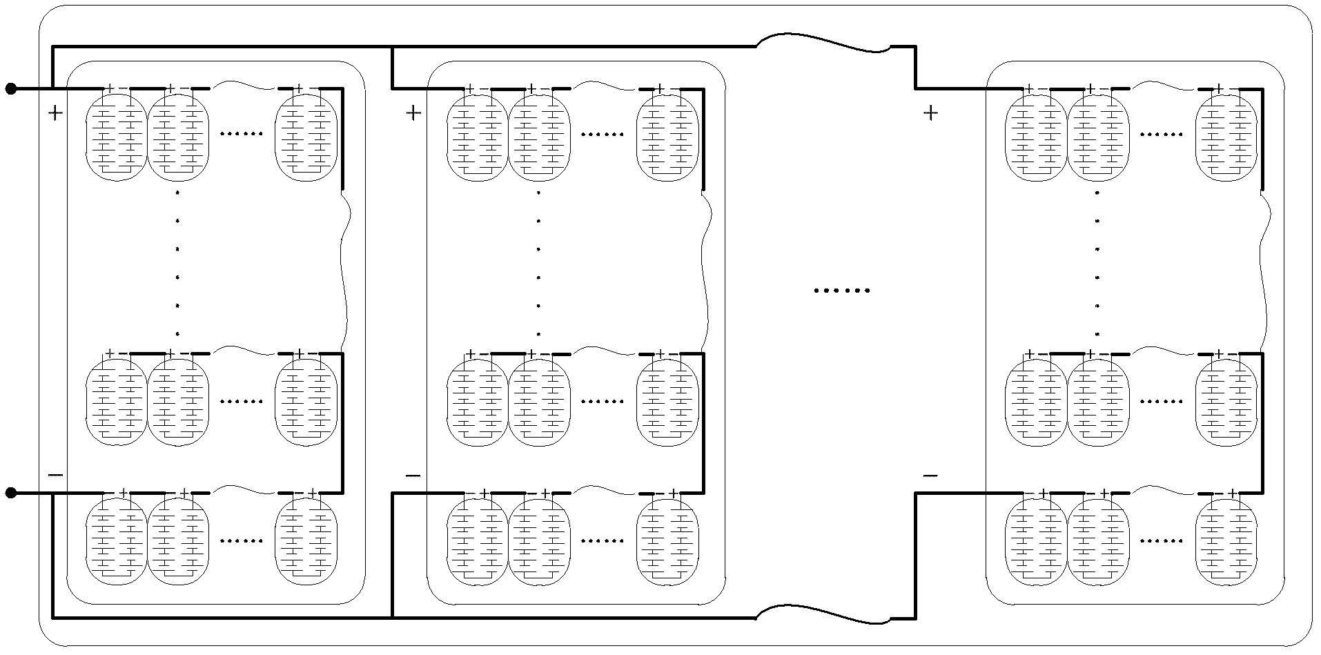
[0028] figure 2 It is the topological structure diagram of the lithium battery system. The lithium battery system is composed of several battery cells in series and parallel, and the specific series and parallel methods are determined by actual needs. Set the system voltage level to u, the voltage of the lithium battery system formed after series-parallel connection is U, and U should not be less than 1.633 times u.

[0029] image 3 It is the topological structure diagram of LCL converter. The LCL convert...


PUM


Abstract

The invention relates to a power conversion system based on energy storage of a lithium battery and a control method of the power conversion system, wherein a lithium battery system is connected to a direct-current end of a converter and is formed by the serial and parallel connection of lithium battery single bodies, and the voltage of the lithium battery system formed by serial and parallel connection is not lower than 1.633 times of a voltage level of a grid system. In the invention, an LCL (inductance capacitance inductance) filter formed by tree groups of series inductors and three capacitors is adopted, every two inductors are connected in series into one inductor group, one end of the each three inductor groups is connected to a three-phase alternating-current output terminal of the converter, respectively, and the other end of the each three inductor groups is respectively connected to a power grid; one ends of the three capacitors are connected with one another to form a common terminal, and the other ends of the three capacitors are respectively connected to the common terminal of the three groups of series inductors. The system and the method carry out SOC (state of charge) monitoring on the battery of the lithium battery system, adopts a current feedback type compensation method to compensate a dead zone, and adopts an SVPWM (space vector pulse width modulation) technology to control the converter. The maximal value of the fundamental wave of the voltage of the output wire of the converter is the voltage of the direct-current side, and is higher than an output voltage of common SPWM converters by 15%.

Description

Technical field [0001] The invention relates to a power conversion system based on lithium battery energy storage and a control method thereof. Background technique [0002] In view of the unpredictability and intermittent problems of electricity generated by most renewable energy power generation devices, domestic and foreign countries have begun to try to solve the bottleneck problem by means of grid transformation, wind power forecasting technology, reserve capacity and large-scale energy storage. Among them, the large-scale energy storage system has the characteristics of good dynamic response characteristics, long life, high reliability, etc., and has attracted attention at home and abroad in the field of improving the capacity of wind power in the grid. At the same time, in recent years, large-capacity battery energy storage technology has been rapidly developed and applied, and the corresponding technical route has gradually become clear. Some typical energy storage batter...

Claims


Application Information

Patent Timeline
Patent Type & Authority Applications(China)
IPC IPC(8): H02J3/28H02M7/5387
Inventor 李建林李蓓马会萌谢志佳惠东
Owner CHINA ELECTRIC POWER RES INST
Learn More