Inductive coupling plasma device

A plasma and inductive coupling technology, applied in the direction of plasma, electrical components, etc., can solve the problem that the plasma distribution has no adjustment effect, and achieve the effect of flexible density distribution, elimination of differences in results, and adjustment of density distribution.

Active Publication Date: 2012-07-11
BEIJING NAURA MICROELECTRONICS EQUIP CO LTD
View PDF7 Cites 10 Cited by
  • Summary
  • Abstract
  • Description
  • Claims
  • Application Information

AI Technical Summary

Problems solved by technology

The more important point is that although the external magnetic field can increase the lifetime of electrons, increase the mean free pa

Method used


Image

  • Inductive coupling plasma device
  • Inductive coupling plasma device
  • Inductive coupling plasma device

Examples


Embodiment Construction

[0026] The specific implementation manners of the present invention will be described in detail below in conjunction with the accompanying drawings.

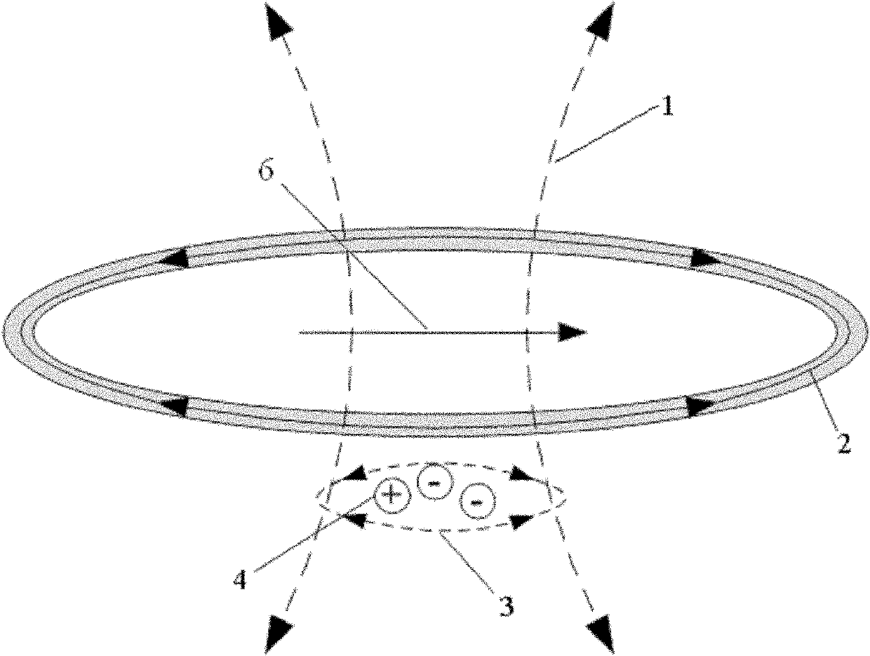
[0027] In the present invention, the inductively coupled plasma device is provided with a compensation adjustment device capable of compensating the influence of the geomagnetic field and adjusting the plasma density distribution, and the compensation adjustment device is arranged outside or inside the inductive coupling generating device.

[0028] Wherein, the inductively coupled plasma device at least includes: a radio frequency main power supply 10 providing radio frequency current, the inductively coupled generating device, a plasma working chamber 19, and an An adjustment bracket 17 for adjusting the height of the plasma working chamber 19.

[0029] The inductive coupling generating device is composed of an inductance coil 22, a quartz dielectric window 18 and a shielding coil box 12 for shielding electromagnetic radiation ...


PUM


Abstract

The invention discloses an inductive coupling plasma device which is designed mainly for overcoming the influences of a geomagnetic field on ICPs (inductively coupled plasmas) and flexibly adjusting distribution of the ICPs. The inductive coupling plasma device at least comprises an inductive coupling generator and a plasma work chamber, wherein the inductive coupling plasma device is arranged at the position of an opening at the top end of the plasma work chamber; a compensation adjustment device is arranged on the inductive coupling plasma device; the compensation adjustment device is arranged outside or inside the inductive coupling generator and is used for compensating influences of the geomagnetic field and adjusting the density distribution of the plasmas. The inductive coupling plasma device can be used for effectively compensating the influences of the density distribution of the plasmas, and can be used for flexibly adjusting the density distribution of the plasmas by adjusting the magnetic strength and the direction of the magnetic field.

Description

technical field [0001] The invention relates to the field of inductively coupled plasma devices, in particular to an inductively coupled plasma device capable of compensating the influence of the geomagnetic field on plasma uniformity. Background technique [0002] Inductively coupled plasma (ICP) was developed rapidly in the 1990s to meet the needs of the development of microelectronics technology. It couples the radio frequency (generally 13.56MHz) power into the vacuum chamber through the inductance coil and the quartz dielectric window, so that the process gas in the chamber is broken down and discharged under the excitation of the induced electric field of the high frequency magnetic field, ionized, and produced high-density plasma. [0003] Such as figure 1 Schematic diagram of the principle of inductively coupled plasma generation shown. The inductance coil is connected to a power supply for providing radio frequency (RF) current. When the inductance coil is suppli...

Claims


Application Information

Patent Timeline
IPC IPC(8): H05H1/16H05H1/46
Inventor 彭东阳
Owner BEIJING NAURA MICROELECTRONICS EQUIP CO LTD
Why Eureka
Try Eureka