
Sintered coupling ring

A technology of clutch teeth and wedge-shaped ends, which is applied to clutches, mechanically driven clutches, vehicle components, etc., can solve problems such as stopper breakage and manufacturing costs, and achieve the effects of improving bearing capacity, simplifying manufacturing requirements, and reducing the risk of breakage

Inactive Publication Date: 2012-07-11
MIBA SINTER AUSTRIA GMBH
View PDF5 Cites 4 Cited by
  • Summary
  • Abstract
  • Description
  • Claims
  • Application Information

AI Technical Summary

Problems solved by technology

These stops are produced by machining the clutch teeth which are sintered with corresponding allowances, which not only entails additional manufacturing costs, but also involves stop breakage when the shifting sleeve abuts against the stop at high speeds danger

Method used


Image

  • Sintered coupling ring
  • Sintered coupling ring
  • Sintered coupling ring

Examples


Embodiment Construction

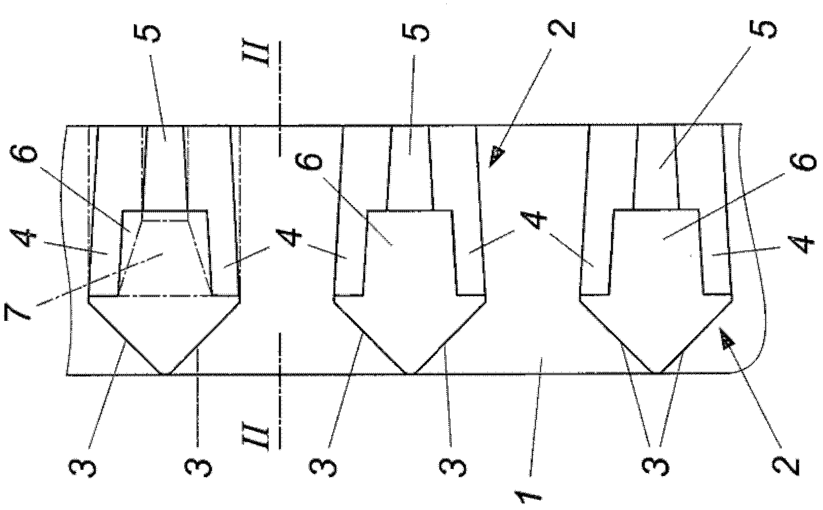
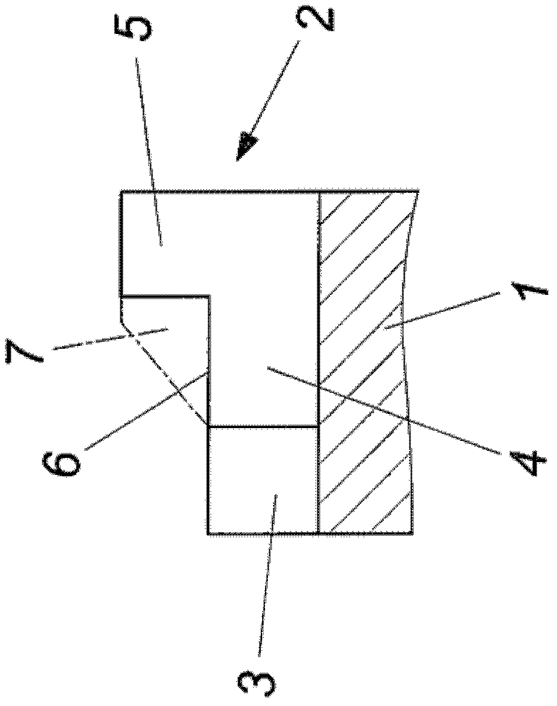
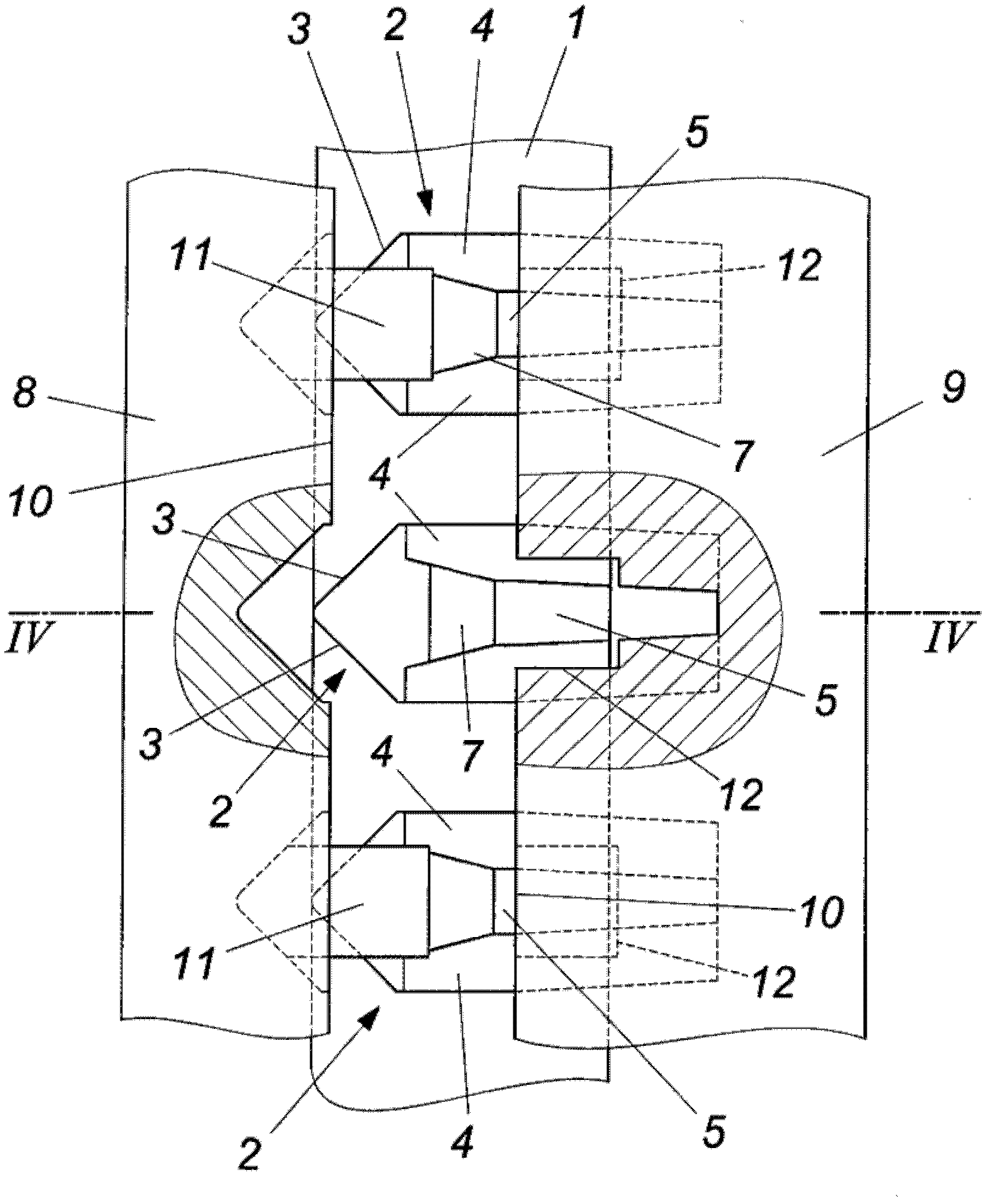
[0014] according to figure 1 with figure 2 The sintered clutch ring 1 has a ring gear consisting of clutch teeth 2 which are formed on the end face of the wedge-shaped end face 3 . A setback flank 4 adjoins this end face 3 . In order to limit the axial movement of the selector sleeve interacting with the clutch ring 1, the clutch tooth 2 is provided with a stop 5 on the end side opposite the wedge-shaped end face 3, as in particular from figure 2 It can be seen that the stop protrudes radially beyond the tooth tip 6 .

[0015] In order to manufacture such a clutch ring 1, a powder blank whose clutch teeth 2 are configured with axially parallel tooth surfaces (such as figure 1 shown by the clutch teeth shown in dotted lines). Furthermore, the stop 5 is extruded and sintered with an allowance 7, which in figure 2 is also shown with a dotted line. When calibrating the sintered molded body, on the one hand the tooth flank indentation is molded and compressed, and on the o...


PUM


Abstract

The invention relates to a sintered coupling ring (1), comprising an annulus of coupling teeth (2), which have flanks (4) that are drawn back and that extend from wedge-shaped end faces (3) and, on the side opposite the wedge-shaped end faces (3), a stop (5) that protrudes radially beyond the tooth tip (6). In order to create advantageous design conditions, the stops (5) have a greater density than the remaining tooth tip (6).

Description

technical field [0001] The invention relates to a sintered clutch ring having a ring gear with clutch teeth having setback tooth flanks starting from a wedge-shaped end face and having radial projections on the side opposite the wedge-shaped end face Stop at the top of the tooth. Background technique [0002] A shift transmission for a vehicle has a clutch ring interacting with a shift sleeve, the clutch teeth of which on the side facing the shift sleeve form a roof-shaped end face arranged in a wedge shape, which enables The engagement of the claws of the shift sleeve in the ring gear of the clutch ring is facilitated. The engagement position of the claws of the shifting sleeve in the axial direction is ensured by the flank indentation of the clutch teeth. In order to produce the flank indentations, during the production of the clutch ring by powder metallurgy, the clutch teeth are subjected to extrusion after sintering of the clutch ring between two dies of a tool which ...

Claims


Application Information

Patent Timeline
Patent Type & Authority Applications(China)
IPC IPC(8): B21K1/30F16D23/02B22F3/16B22F5/08
CPCB22F5/08B21J5/002B22F2998/10B21K1/30F16D23/025F16D2023/0656F16D2023/0668B22F3/02B22F3/16
Inventor C·克朗伯格H·罗斯勒C·桑德纳
Owner MIBA SINTER AUSTRIA GMBH
Learn More