Grinder
A pulverizer and casing technology, applied in the field of biomass pulverizing devices, can solve the problems of inconvenient collection, equipment damage, and the difficulty of manual feeding, and achieve the effects of convenient transportation, convenient hitting of materials, and convenient collection.
- Summary
- Abstract
- Description
- Claims
- Application Information
AI Technical Summary
Problems solved by technology
Method used
Image

Examples
Embodiment 1
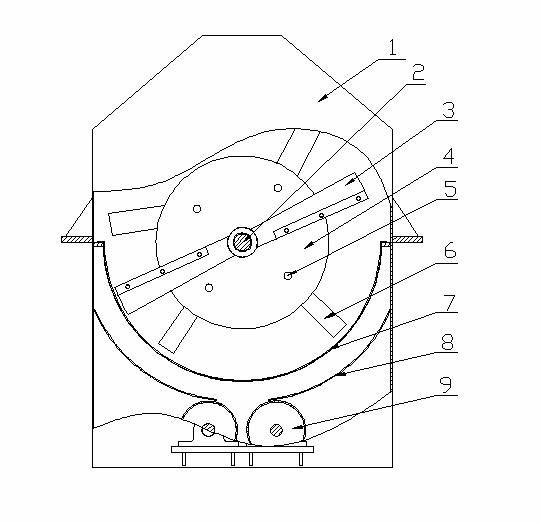
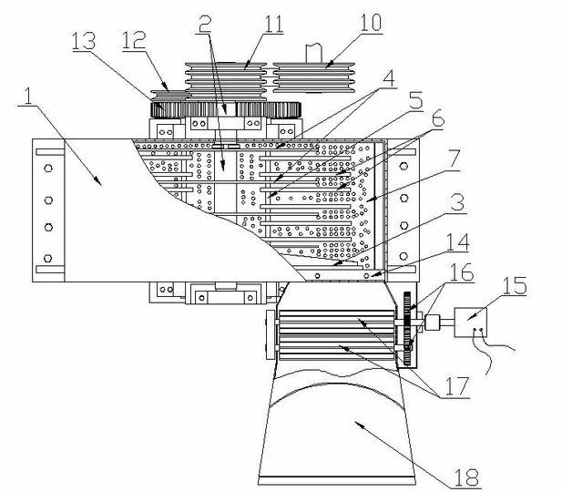
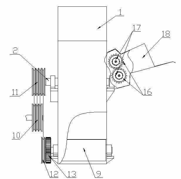
[0032] A pulverizer, comprising a casing, a feed port on the side of the casing, a discharge port at the bottom of the casing, a main drive, a feed drive, a main shaft, a first pressing roller, a second pressing roller, a disc, a round The disk is connected to the shaft and the beating sheet. The first pressure roller is driven by the feed transmission device and is located in the feed inlet. The second pressure roller is driven by the main transmission device and is located in the discharge opening. The two disks are It is set on the main shaft and located in the casing, the discs are connected by two disc connecting shafts, the hitting piece is fixedly arranged on the disc connecting shaft, the main shaft is driven by the main transmission device, and it is also fixed on the main shaft The first cutter is located in the casing, the main shaft passes through the casing, and is rotatably connected with the casing.
Embodiment 2
[0034] A pulverizer, comprising a casing, a feed port on the side of the casing, a discharge port at the bottom of the casing, a main drive, a feed drive, a main shaft, a first pressing roller, a second pressing roller, a disc, a round The disk is connected to the shaft and the beating sheet. The first pressure roller is driven by the feed transmission device and is located in the feed inlet. The second pressure roller is driven by the main transmission device and is located in the discharge outlet. The three disks are It is set on the main shaft and located in the casing. The discs are connected by three disc connecting shafts. The hitting piece is fixedly arranged on the disc connecting shafts. The main shaft is driven by the main transmission device. The first cutter is located in the casing, the main shaft passes through the casing, and is rotatably connected with the casing. The first cutter is arranged at the end of the main shaft close to the feed inlet, and is located ...
Embodiment 3
[0036] A pulverizer, comprising a casing, a feed port on the side of the casing, a discharge port at the bottom of the casing, a main drive, a feed drive, a main shaft, a first pressing roller, a second pressing roller, a disc, a round The disk is connected to the shaft and the beating sheet. The first pressure roller is driven by the feed transmission device and is located in the feed inlet. The second pressure roller is driven by the main transmission device and is located in the discharge opening. The two disks are It is set on the main shaft and located in the casing, the discs are connected by two disc connecting shafts, the hitting piece is fixedly arranged on the disc connecting shaft, the main shaft is driven by the main transmission device, and it is also fixed on the main shaft The first cutter is located in the casing, the main shaft passes through the casing, and is rotatably connected with the casing. The first cutter is arranged at the end of the main shaft close...
PUM
 Abstract
Description
Claims
Application Information
 - R&D
- Intellectual Property
- Life Sciences
- Materials
- Tech Scout
- Unparalleled Data Quality
- Higher Quality Content
- 60% Fewer Hallucinations
Browse by: Latest US Patents, China's latest patents, Technical Efficacy Thesaurus, Application Domain, Technology Topic, Popular Technical Reports.
© 2025 PatSnap. All rights reserved.Legal|Privacy policy|Modern Slavery Act Transparency Statement|Sitemap|About US| Contact US: help@patsnap.com