
Rotary spraying-flushing device lifted by water power

A hydraulic and ball-spraying technology, which is applied to spraying devices, spraying devices with movable outlets, cleaning hollow objects, etc., can solve the problems of incomplete cleaning of the inner wall of beverage bottles, limited water column height, and insufficient strength, etc., to achieve cleaning efficiency Excellent, compact structure, comprehensive flushing effect

Inactive Publication Date: 2012-07-18
GUANGZHOU TECH LONG PACKAGING MACHINERY CO LTD
View PDF4 Cites 5 Cited by
  • Summary
  • Abstract
  • Description
  • Claims
  • Application Information

AI Technical Summary

Problems solved by technology

[0002] During the cleaning process of the beverage bottle, the nozzle needs to be aimed at the inside of the beverage bottle. Since the spraying device is sprayed from bottom to top, limited by gravity, the height of the water column sprayed by the nozzle is limited, and at the end, due to insufficient force Resulting in incomplete cleaning of the inner wall of the beverage bottle
In addition, the jet flow of the existing nozzle only impacts and does not rotate, so streaks are often left after cleaning the scales on the pipe wall, resulting in unclean cleaning
If the nozzle is extended, it is necessary to replace the corresponding nozzle when changing different beverage bottles, which makes it extremely inconvenient to use

Method used


Image

  • Rotary spraying-flushing device lifted by water power
  • Rotary spraying-flushing device lifted by water power
  • Rotary spraying-flushing device lifted by water power

Examples


Embodiment Construction

[0019] The structure of the hydraulic lifting rotary spraying device is as follows:

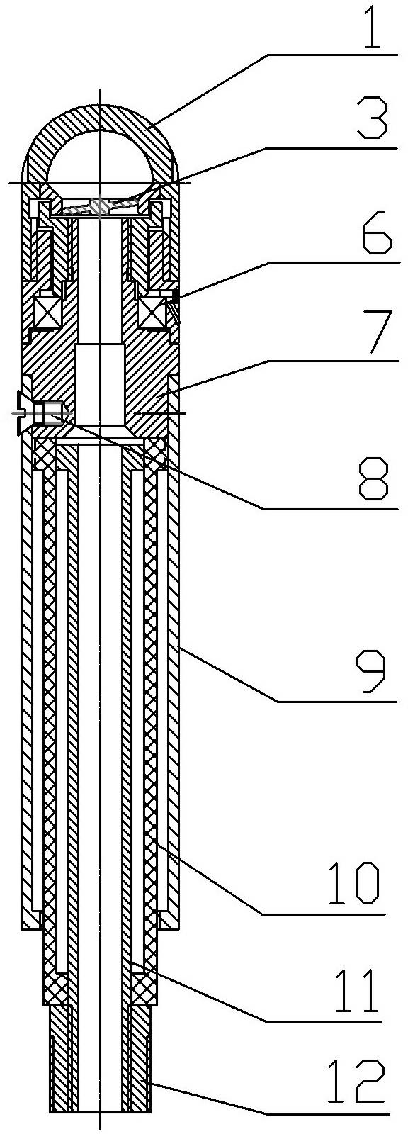
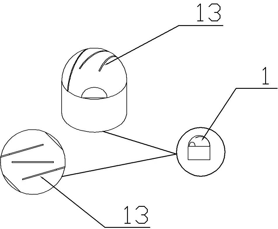
[0020] Such as figure 1 , 2 As shown, in the rotary spraying device, an inner slide 11 is connected with an external water pipe through a pipe joint 12 to transmit water for spraying, and a middle slide 10 is sleeved on the inner slide 11 and can be moved along the It slides up and down, a connecting seat 7 is fixedly set in the outer sliding cylinder 9 by screws 8, and its interior is hollow for water to flow through, a deep groove ball bearing 6 is set and fixed on the connecting seat 7, and the spray ball joint 5 is installed on the The outer side of the deep groove ball bearing 6 can freely rotate in the forward or reverse direction. The inside of the fixed joint is hollow, one end of which extends into the spray ball joint 5, and the other end is inserted into the rotating spray ball 1 and can guide the water introduced in the sliding cylinder to Spray from the rotating spray ball 1, s...


PUM


Abstract

The invention discloses a rotary spraying-flushing device lifted by water power. An outer sliding sleeve is sleeved on an inner sliding sleeve and can slide up and down along the inner sliding sleeve; a bearing is arranged on the outer surface of the water outlet end of the outer sliding sleeve; a rotary spraying ball is fixed at the outer side of the bearing; and a plurality of irregular holes are arranged on the side wall of the rotary spraying ball. The rotary spraying-flushing device lifted by the water power has the advantages that: 1, when water is sprayed, a sleeve pipe can be driven by the water power to extend upwards, so that the sleeve pipe has the function of increasing the height; and an impeller of the rotary spraying-flushing device and gaps on a spraying nozzle can cause the water flowing through a spraying pipe to obtain a rotation function; 2, the flowing route in the spraying pipe can be lengthened by the sleeve pipe, so that the rotary spraying-flushing device has the advantage of low energy consumption; 3, the rotary spraying-flushing device can achieve thorough flushing and can flush parts with any angle, and the cleaning efficiency is excellent; and 4, the rotary spraying-flushing device is compact in structure, can be driven by cleaning solution and has the advantages of self-lubrication and self-rotation.

Description

technical field [0001] The invention relates to a spraying device, in particular to a hydraulically lifting rotary spraying device. Background technique [0002] During the cleaning process of the beverage bottle, the nozzle needs to be aimed at the inside of the beverage bottle. Since the spraying device is sprayed from bottom to top, limited by gravity, the height of the water column sprayed by the nozzle is limited, and at the end, due to insufficient force As a result, the inner wall of the beverage bottle cannot be completely cleaned. In addition, the jet flow of the existing nozzle only impacts and does not rotate, so streaks are often left after cleaning the fouling on the pipe wall, resulting in unclean cleaning. If the nozzle is lengthened, the corresponding nozzle needs to be replaced when changing different beverage bottles, which is extremely inconvenient to use. Contents of the invention [0003] The technical problem to be solved by the present invention is...

Claims


Application Information

Patent Timeline
Patent Type & Authority Applications(China)
IPC IPC(8): B08B9/093B05B3/02
Inventor 刘方城吴锡林苏继前
Owner GUANGZHOU TECH LONG PACKAGING MACHINERY CO LTD
Learn More