Supercharge Your Innovation With Domain-Expert AI Agents!

Improved annular jaw splice piece of hydraulic draw-bench

A technology of inserting and hydraulic pressure, which is applied in the field of inserting the ring jaw of the improved hydraulic puller, can solve the problems of increased product cost, increased steel pipe head forging, cutting process, and decreased steel pipe yield, so as to improve the cost rate , Prevent deformation of the steel pipe and increase the effect of clamping force

Inactive Publication Date: 2012-07-18
宜兴市景程模具有限公司
View PDF7 Cites 2 Cited by
  • Summary
  • Abstract
  • Description
  • Claims
  • Application Information

AI Technical Summary

Problems solved by technology

[0002] At present, the hydraulic inserts of hydraulic drawing machines on the market generally have two sheet structures. When the inserts clamp the head of the steel pipe, because only two sides are clamped, the head of the steel pipe must be forged to make the head forged. The punching and the insert fit each other to clamp the steel pipe. Due to forging, the head of the steel pipe is deformed, and the deformed head of the processed steel pipe needs to be cut off, so that the yield of the steel pipe is reduced, and the forging of the steel pipe head is increased. Beating and cutting processes, the overall product cost has also increased

Method used


Image

  • Improved annular jaw splice piece of hydraulic draw-bench
  • Improved annular jaw splice piece of hydraulic draw-bench
  • Improved annular jaw splice piece of hydraulic draw-bench

Examples


Embodiment Construction

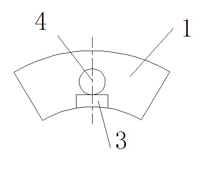
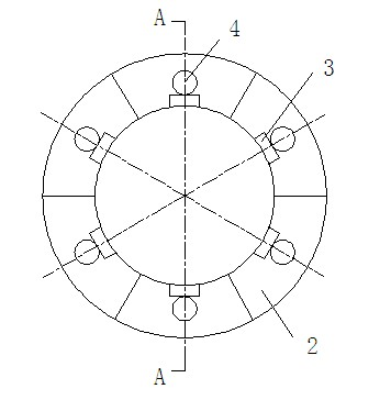
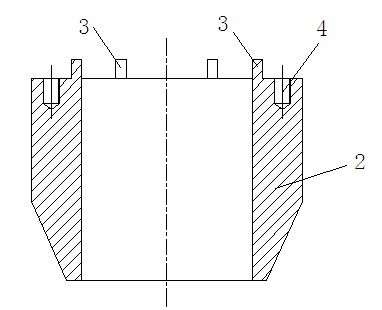
[0015] Such as figure 1 , 2 1. An improved annular jaw insert of a hydraulic puller shown in 3, the insert is composed of two or three fan rings 1, and the fan ring 1 is a matrix with a cylinder at the top and a cone at the bottom with a circular hole in the middle 2, the center of the top surface of each fan ring 1 is provided with square bumps 3 distributed in the same circular track along the inner circumference, and a threaded hole 4 is arranged concentrically on the outside of the square bumps. The square bumps 3 Matched with the threaded hole 4 and the jaw of the hydraulic puller, the hollow base 2 is divided into 2-6 pieces. When the base is divided into 2 pieces, the cut part of each semicircular base 2 is a fan ring 1, forming the 2 of the insert -Three fan rings 1 are fitted on the jaws of the hydraulic drawing machine at intervals of the same circular track, and the base body 1 is 45 steel with surface carburizing treatment.

[0016] When making this improved hydr...


PUM


Abstract

The invention discloses an improved annular jaw splice piece of a hydraulic draw-bench. The improved annular jaw splice piece of the hydraulic draw-bench comprises two or three fan rings. The fan rings are equal parts of a base. Each one of the fan rings has a cylindrical upper part and a conical lower part and is provided with a screwed round hole in a middle part. Square lugs are arranged on centers of top surfaces of the fan rings along inner circumferences and are distributed along the same circle locus. The screwed round holes are concentrically arranged closely to outer sides of the square lugs. The square lugs and the screwed round holes match with a hydraulic draw-bench grip. The improved annular jaw splice piece of the hydraulic draw-bench is designed into a fan ring contacting with an external diameter line of a steel pipe so that a clamping force is greatly increased; deformation of the steel pipe is effectively avoided; a cost rate is improved; and use is convenient.

Description

technical field [0001] The invention relates to a clamping device on a hydraulic pulling machine, in particular to an improved annular jaw insert of a hydraulic pulling machine. Background technique [0002] At present, the hydraulic inserts of hydraulic drawing machines on the market generally have two sheet structures. When the inserts clamp the head of the steel pipe, because only two sides are clamped, the head of the steel pipe must be forged to make the head forged. The punching and the insert fit each other to clamp the steel pipe. Due to forging, the head of the steel pipe is deformed, and the deformed head of the processed steel pipe needs to be cut off, so that the yield of the steel pipe is reduced, and the forging of the steel pipe head is increased. Hitting, cutting process, the overall product cost has also increased. Contents of the invention [0003] Aiming at the disadvantages of the prior art, the invention provides an improved annular jaw insert of a hy...

Claims


Application Information

Patent Timeline
IPC IPC(8): B21C1/28B21C1/22
Inventor 邓毅敏殷世春
Owner 宜兴市景程模具有限公司
Features
  • R&D
  • Intellectual Property
  • Life Sciences
  • Materials
  • Tech Scout
  • Unparalleled Data Quality
  • Higher Quality Content
  • 60% Fewer Hallucinations
Learn More