
Internal cooling structure with grooves and ribs on front edge of turbine blade and method of internal cooling structure

A turbine blade and leading edge technology, applied in the field of internal cooling structure, can solve the problems of low yield, complex blade processing technology, lower gas temperature, etc., and achieve the effect of increasing turbine inlet temperature, easy promotion and use, and prolonging service life

Inactive Publication Date: 2014-11-05
NANJING UNIV OF AERONAUTICS & ASTRONAUTICS
View PDF6 Cites 0 Cited by
  • Summary
  • Abstract
  • Description
  • Claims
  • Application Information

AI Technical Summary

Problems solved by technology

The cooling effect obtained by this external cooling technology is significantly better than that of internal cooling technology, and has been widely used in modern high-performance gas turbines, but it also has several insurmountable shortcomings: one is that the cooling gas flows to the outside of the blades It has an adverse effect on high-temperature gas, which not only produces mixing loss but also reduces the temperature of the gas, making it difficult to guarantee the design performance of the original aerodynamic profile of the turbine blade, thereby reducing the thermal efficiency and output power of the gas turbine; the second is the air-cooled turbine The blade itself is a hollow thin-walled part with extremely irregular shape, and the opening of air film holes on it greatly increases the manufacturing difficulty, resulting in complex processing technology, low yield and high cost of the blade; the third is the air film hole It is easy to be blocked by solid particles such as smoke and dust, causing the blades to be burned due to insufficient cooling, making it unsuitable for gas turbines to work in a dirty near-surface atmospheric environment for a long time. It is also more dangerous for land-use heavy-duty gas turbines powered by fuel, and the turbine blades must be cleaned and maintained frequently during use

Method used


Image

  • Internal cooling structure with grooves and ribs on front edge of turbine blade and method of internal cooling structure
  • Internal cooling structure with grooves and ribs on front edge of turbine blade and method of internal cooling structure
  • Internal cooling structure with grooves and ribs on front edge of turbine blade and method of internal cooling structure

Examples


Embodiment Construction

[0024] The present invention will be further described below in conjunction with the accompanying drawings and embodiments.

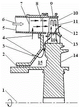
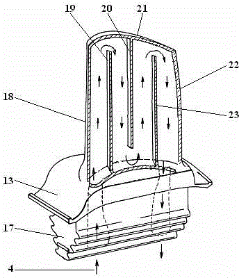
[0025] figure 1 The structure of the high-pressure turbine components of the gas turbine is shown, and the guide vane 7 and the rotor blade 10 are two important components thereof. The high-temperature gas 6 enters the cascade passage through the inlet 5 of the high-pressure turbine component, and the cascade passage is composed of guide vanes, rotor blades, turbine casing 9, moving blade hub 13, stator blade inner edge plate 24 and stator blade outer edge plate 26, etc. formed around. The guide vane converts the thermal energy of the gas into its kinetic energy and adjusts it to an appropriate angle to impinge on the downstream rotor blades, and the rotor blades extract the kinetic energy from the gas to rotate at high speed. The rotor blades are fixed on the turbine disk 14 through their moving blade tenons 17, so the rotor blades drive the turbine ...


PUM


Abstract

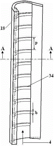
The invention relates to an internal cooling structure with grooves and ribs on a front edge of a turbine blade and a method of the internal cooling structure, which belong to the technical field of internal cooling of turbine blades. A groove structure is arranged on the inner wall surface of the front edge of a rotor blade (10) along a blade height direction, and a plurality of arc-shaped ribs (34) are parallelly distributed in the groove structure in a direction perpendicular to the blade height direction; another groove structure is arranged on the inner wall surface of the front edge of a guiding blade (7) along a blade height direction, and a plurality of arc-shaped ribs (34) are parallelly distributed in the groove structure in a direction perpendicular to the blade height direction; and impact holes (29) on inserts (28) and the arc-shaped ribs (34) are arrayed in a staggered manner. Two strengthened cooling measures are comprehensively taken by the aid of the grooves and the ribs, the front edge of the blade can be cooled down better, furthermore, the cooling structure and the blade are integrated, so that the turbine blade is simpler in structure, and the weight of the turbine blade is reduced effectively under the condition that the strength of the turbine blade is guaranteed.

Description

technical field [0001] The invention relates to an internal cooling structure of a gas turbine, especially a turbine blade of a heavy-duty land-use gas turbine. Specifically, it relates to a sinker rib internal cooling structure applied to the leading edge of the turbine blade. Background technique [0002] A gas turbine is an advanced power machine that converts thermal energy into mechanical energy. One of the main ways to improve its energy conversion efficiency is to increase the gas temperature before the turbine, but this also leads to the deterioration of the working environment of high-temperature turbine components. At present, the gas temperature before the turbine of advanced gas turbine exceeds 1500°C, which is far higher than the melting temperature of the turbine material. In order to ensure the safe, reliable and long-term operation of the gas turbine, it is necessary to effectively cool the high-temperature turbine components. Among them, the cooling of turbi...

Claims


Application Information

Patent Timeline
Patent Type & Authority Patents(China)
IPC IPC(8): F01D5/18F01D9/02
Inventor 吉洪湖朱强华
Owner NANJING UNIV OF AERONAUTICS & ASTRONAUTICS
Learn More