Cantilever crane system, engineering machinery and cantilever crane system terminal end location parameter obtaining method

A technology of end position and boom, which is applied in the acquisition of end position parameters of construction machinery and boom systems, and in the field of boom systems, which can solve problems such as large deviations and inability to meet accurate positioning and control of the end of the boom system

Active Publication Date: 2014-05-21
SANY HEAVY IND CO LTD (CN)
View PDF5 Cites 0 Cited by
  • Summary
  • Abstract
  • Description
  • Claims
  • Application Information

AI Technical Summary

Problems solved by technology

Although this method can improve the accuracy of the position parameters at the end of the boom system, due to the limitation of the measurement accuracy of the inclination sensor, the deviation between the position parameters at the end of the boom system and the target position parameters is still large, which cannot meet the requirements of the boom system. The need for accurate positioning and control of the tip

Method used


Image

  • Cantilever crane system, engineering machinery and cantilever crane system terminal end location parameter obtaining method
  • Cantilever crane system, engineering machinery and cantilever crane system terminal end location parameter obtaining method
  • Cantilever crane system, engineering machinery and cantilever crane system terminal end location parameter obtaining method

Examples


Embodiment Construction

[0043] In order to understand the above-mentioned purpose, features and advantages of the present invention more clearly, the present invention will be further described in detail below in conjunction with the accompanying drawings and specific embodiments.

[0044] In the following description, many specific details are set forth in order to fully understand the present invention, but the present invention can also be implemented in other ways different from those described here, therefore, the present invention is not limited to the specific embodiments disclosed below limit.

[0045] In order to describe the technical solution provided by the present invention more clearly, this part first describes the boom system provided, and describes the method for obtaining the end position parameters of the boom system on the basis of the description of the boom system; obtaining the boom system The method for providing terminal position parameters can be implemented by using the boo...


PUM


Abstract

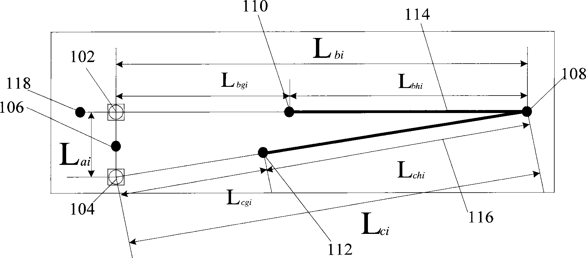
A boom system comprising multiple boom sections hingedly connected in sequence via a horizontal hinge shaft, also comprising: two length sensors (102 and 104) arranged on each of the boom sections, where one sensor (102) measures the length of the corresponding boom section after a shape-change, while the other length sensor (104) measures the length between same and the distal end of the corresponding boom section, and where the two length sensors (102 and 104) are provided therebetween with a predetermined distance; a tilt angle sensor (106) arranged on each of the boom sections, for acquiring the angle between a reference plane and a line running between the two length sensors (102 and 104); and a processor (200) that acquires an distal end position parameter of the boom system on the basis of the measurement results of the tilt angle sensor (106) and of the length sensors (102 and 104). On the basis of the boom system, the distal end position parameter of the boom is acquired by using for a single boom one tilt angle sensor and two pull encoders, thus increasing the precision in acquiring the distal end position parameter of the boom system. Also provided are an engineering machinery and a method for acquiring the distal end position parameter of the boom system.

Description

technical field [0001] The invention relates to the technical field of boom control, in particular to a boom system, an engineering machine and a method for acquiring end position parameters of the boom system. Background technique [0002] As a mobile material transportation equipment, the multi-joint robotic arm is widely used in concrete transportation, high-altitude fire-fighting operations, port oil supply and other fields due to its strong versatility, wide operating range, and flexible operation. It has become an indispensable high-end in national construction. technical equipment. [0003] The boom system generally includes a multi-section boom, the big end of the first section arm is hinged with the predetermined chassis through a vertical axis; the big end of other section arms is hinged with the small end of the adjacent section arm through a horizontal hinge axis In this way, the multi-section arms are sequentially hinged and connected through the horizontal hin...

Claims


Application Information

Patent Timeline
Patent Type & Authority Patents(China)
IPC IPC(8): G01B21/00
CPCB66C23/00E04G21/0463B66C23/905B66F11/00E04G21/04E04G21/0445G01B21/16G01B21/22
Inventor 易小刚张作良李东徐增丙
Owner SANY HEAVY IND CO LTD (CN)
Why Eureka
Try Eureka