
A kind of measuring method of axial refractive index of anisotropic semiconductor optical film

An optical film and anisotropic technology, applied in the field of vacuum ultraviolet optical detection, can solve the problems of low measurement accuracy, achieve high measurement accuracy, solve the problem of inaccurate measurement, and have broad application prospects

Active Publication Date: 2022-06-03
SUN YAT SEN UNIV
View PDF11 Cites 0 Cited by
  • Summary
  • Abstract
  • Description
  • Claims
  • Application Information

AI Technical Summary

Problems solved by technology

[0004] The invention provides a method for measuring the axial refractive index of anisotropic semiconductor optical films in order to overcome the technical defect of low measurement accuracy of the existing spectroscopic ellipsometer for measuring the refractive index of anisotropic films

Method used


Image

  • A kind of measuring method of axial refractive index of anisotropic semiconductor optical film
  • A kind of measuring method of axial refractive index of anisotropic semiconductor optical film
  • A kind of measuring method of axial refractive index of anisotropic semiconductor optical film

Examples


Embodiment 1

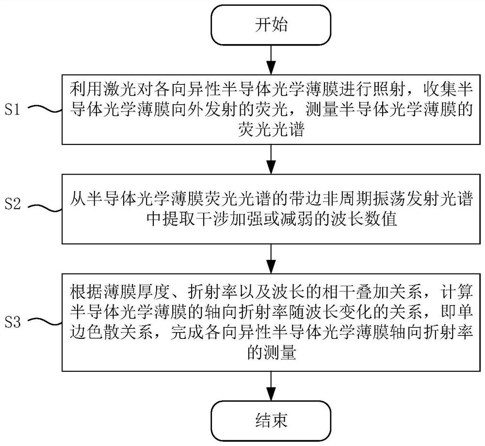
[0037] like figure 1 Shown, a kind of measuring method of axial refractive index of anisotropic semiconductor optical film is characterized in that, comprises the following steps:

[0038] S1: Use laser light to irradiate the anisotropic semiconductor optical film, collect the fluorescence emitted by the semiconductor optical film, and measure the fluorescence spectrum of the semiconductor optical film;

[0039] S2: Extract the wavelength value of the interference enhancement or weakening from the band-edge aperiodic oscillation emission spectrum of the semiconductor optical thin film fluorescence spectrum;

[0040] S3: According to the coherent superposition relationship of film thickness, refractive index and wavelength, calculate the relationship between the axial refractive index of the semiconductor optical film and the wavelength, that is, the unilateral dispersion relationship, and complete the measurement of the axial refractive index of the anisotropic semiconductor o...

Embodiment 2

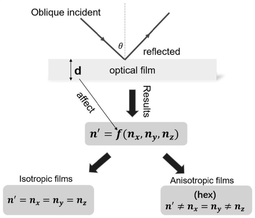
[0056] On the basis of Example 1, hexagonal aluminum nitride (AIN) was chosen as an example to measure its refractive index. like figure 2 as shown, figure 2 It is a schematic diagram for measuring the refractive index of a spectroscopic ellipsometer. When the incident light is obliquely incident on the sample surface, the measured refractive index is usually the "apparent refractive index" n', which is a refractive index about the x-axis (n x ), the y-axis refractive index (n y ) and z-axis refractive index (n z ) function (n′=f(n x ,n y ,n z )). For isotropic semiconductor optical films, such as Si and diamond, the "apparent refractive index" is equivalent to the crystal axis refractive index, that is, n'=n x =n y =n z . In order to obtain the crystal axis refractive index of the anisotropic film, it is necessary to measure the polarization of the reflected light (o light) parallel to the incident plane (o light) and the reflected light perpendicular to the incid...


PUM

PropertyMeasurementUnit
thicknessaaaaaaaaaa
thicknessaaaaaaaaaa

Abstract

The invention provides a method for measuring the axial refractive index of an anisotropic semiconductor optical film, comprising the following steps: irradiating the anisotropic semiconductor optical film with laser light, collecting the fluorescence emitted by the semiconductor optical film, and measuring the semiconductor optical film The fluorescence spectrum of the semiconductor optical film; extract the wavelength value of the interference enhancement or weakening from the band-edge aperiodic oscillation emission spectrum of the semiconductor optical thin film fluorescence spectrum; calculate the axial refractive index of the semiconductor optical thin film according to the coherent superposition relationship of film thickness, refractive index and wavelength The relationship with the change of wavelength, that is, the unilateral dispersion relationship, completes the measurement of the axial refractive index of anisotropic semiconductor optical films. The measurement method provided by the invention can be applied to the anisotropic wide-bandgap semiconductor optical film, has high measurement accuracy, solves the technical problem that the band-edge refractive index cannot be accurately measured, and has broad application prospects.

Description

technical field [0001] The invention relates to the technical field of vacuum ultraviolet optical detection, and more specifically, relates to a method for measuring the axial refractive index of an anisotropic semiconductor optical film. Background technique [0002] The refractive index and extinction coefficient are a group of crucial and closely related optical constants, which have a significant impact on the light extraction efficiency of light-emitting diodes, the photoelectric conversion efficiency of solar cells, and the quantum efficiency of photodetectors. Therefore, the accurate measurement of optical constants has always occupied an important position in the field of optoelectronics. Theoretically, optical constants such as refractive index can be obtained through the Kramer-Kronig transformation relationship, which does not depend on specific physical models, and the functional relationship and internal relationship between optical constants can be deduced pure...

Claims


Application Information

Patent Timeline
Patent Type & Authority Patents(China)
IPC IPC(8): G01N21/41G01N21/45
CPCG01N21/4133G01N21/45Y02E10/50
Inventor 郑伟朱燕明林日成黄丰
Owner SUN YAT SEN UNIV
Learn More