Element and method for discriminating fault electrode of DC transmission line

A technology for DC transmission lines and fault poles, which is applied in the direction of measuring electricity, measuring electrical variables, measuring devices, etc., can solve the problems of unfavorable DC transmission project safety and stability, sound pole outage, and low reliability, etc., to improve safety and stability. performance, preventing malfunction, and reliable principle

Inactive Publication Date: 2012-07-18
XI AN JIAOTONG UNIV +1
View PDF7 Cites 17 Cited by
  • Summary
  • Abstract
  • Description
  • Claims
  • Application Information

AI Technical Summary

Problems solved by technology

[0008] Most of the existing DC transmission projects are bipolar systems, and as the voltage level increases, the coupling effect between the lines also increases. When a fault occurs in a pole line, the faulty pole is coupled to the sound pole It is very likely that the voltage and current components of the healthy pole will cause malfunction of the line protection of the healthy pole, resulting in the outage of the healthy pole.
However, it can be seen from the above protection principles that the existing DC transmission project line protection does not have the principle and components to distinguish the faults of the local pole and the fault of the opposite pole, the reliability is not high, and it is not conducive to the safety and stability of the DC transmission project.

Method used


Image

  • Element and method for discriminating fault electrode of DC transmission line
  • Element and method for discriminating fault electrode of DC transmission line
  • Element and method for discriminating fault electrode of DC transmission line

Examples


Embodiment Construction

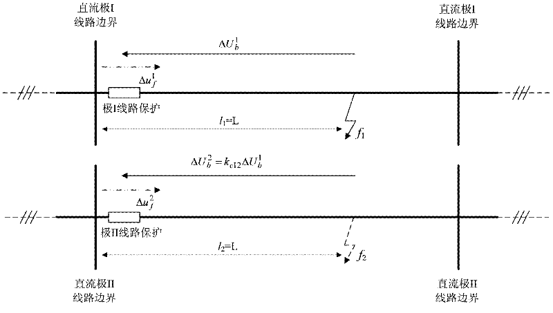
[0036] as attached figure 1 As shown, the line protection is installed on the rectification side of the system, and the positive direction of the current is specified as the DC polarity busbar flows to the line. When the state signal propagates along the line, a strong transient signal will be induced on the other pole line. The transient signal detected by the protection after the fault occurs is a comprehensive signal composed of forward wave and backward wave, which reflects the complex refraction and reflection process of the line boundary, and the line fault always occurs in the positive direction specified by the protection of the pole where the fault is located. Upward, the traveling wave signal detected by the protection for the first time must come from the anti-traveling wave in the positive direction, so the anti-traveling wave can be used to distinguish the faulty pole from the healthy pole. as attached figure 1 As shown in , assuming that a ground fault occurs a...


PUM


Abstract

The invention discloses an element and a method for discriminating a fault electrode of an ultra-high-speed DC transmission line based on a single-end transient signal. The fault electrode discriminating element comprises a fault component computing element, a backward traveling wave energy computing unit and a comparing and order-issuing unit. The method comprises the following steps of: discriminating a fault electrode and a normal electrode of a DC transmission line by using a backward traveling wave energy value and a threshold value subjected to comparative calculation; if the backward traveling energy value is more than the threshold value, judging that the operation electrode of the DC transmission line is the fault electrode; or else, judging the operation electrode of the DC transmission line is the normal electrode and sending out corresponding commands. The test result shows that the fault electrode discriminating element of the DC transmission line can be used for accurately discriminating the fault electrodes and the normal electrodes in different DC transmission projects and in different operation conditions of the DC transmission project only by using single-end voltage and current signals of a line and is not subjected to the influences of fault positions and transition resistors; the protecting and setting workload for different DC transmission projects is low and the workloads of protection workers and on-site operating staff are reduced.

Description

Technical field: [0001] The invention belongs to the field of protection of high-voltage transmission lines in electric power systems, and relates to a line protection method for rapid detection of faults in the local and opposite poles of a DC line, in particular to a method for realizing an ultra-high-speed DC line fault pole discrimination element based on transient signals. Background technique: [0002] With its advantages of large transmission capacity, high stability, fast control response, and no increase in the short-circuit capacity of the connected grid after networking, DC transmission has played a very important role in implementing the strategy of west-to-east power transmission in my country and realizing the national networking project. So far, my country not only has more than 20 ±500kV HVDC transmission lines such as Gezhouba-South Bridge, Tianshengqiao-Guangzhou, Deyang-Baoji, Three Gorges-Changzhou, Three Gorges-Shanghai, Three Gorges-Guangdong, and Zhoush...

Claims


Application Information

Patent Timeline
Patent Type & Authority Applications(China)
IPC IPC(8): G01R31/00G01R31/02
Inventor 张保会郝治国甄威孔飞
Owner XI AN JIAOTONG UNIV
Why Eureka
Try Eureka