Grid for radiography, radiation image detector, radiation imaging system, and method for manufacturing grid

A technology of an image detector and an imaging system, which is applied to instruments for radiological diagnosis, material analysis using radiation diffraction, diffraction gratings, etc. High and low cost effect

Inactive Publication Date: 2012-07-18
FUJIFILM CORP
View PDF6 Cites 19 Cited by
  • Summary
  • Abstract
  • Description
  • Claims
  • Application Information

AI Technical Summary

Problems solved by technology

However, neither Japanese Patent Laid-Open No. 2002-334977 nor Applied Physics Letters (Applied Physics Letters) Vol. 69, No. 18, p. 2629 discloses a specific method for preparing a grid

Method used


Image

  • Grid for radiography, radiation image detector, radiation imaging system, and method for manufacturing grid
  • Grid for radiography, radiation image detector, radiation imaging system, and method for manufacturing grid
  • Grid for radiography, radiation image detector, radiation imaging system, and method for manufacturing grid

Examples


no. 1 approach

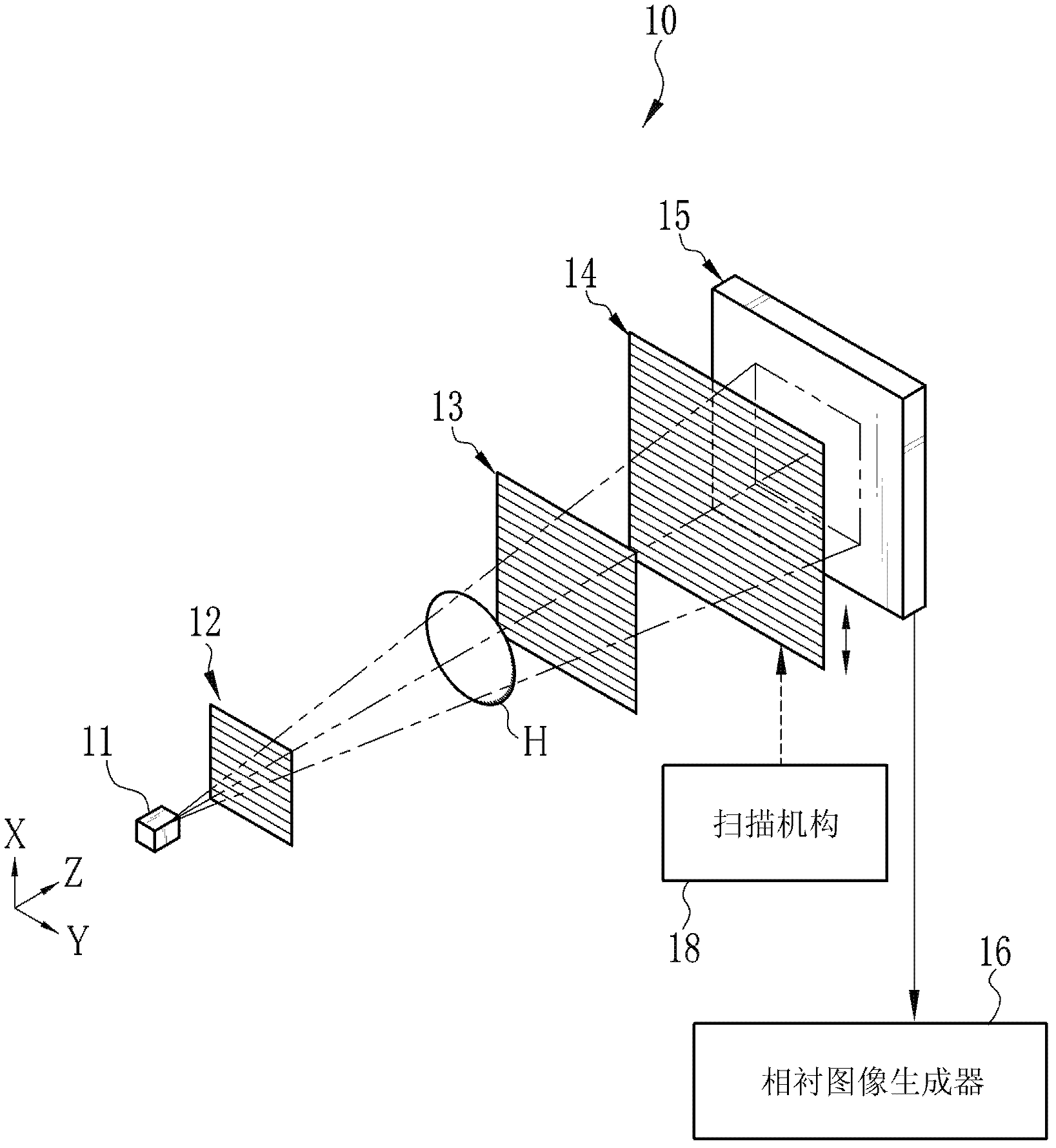
[0041] Such as figure 1 As shown in , the X-ray imaging system 10 is composed of the following items: X-ray source 11, source grid 12, first grid 13, second grid 14 and X-ray image detector 15, which are arranged as X-ray in the Z direction of the propagation direction. The X-ray source 11 has, for example, a rotating anode type X-ray tube, and a collimator for confining a radiation field of X-rays and applying an X-ray cone beam to the sample H. The X-ray image detector 15 is a flat panel detector (FPD) composed of, for example, a semiconductor circuit, and is disposed behind the second grid 14 . A phase-contrast image generator 16 is connected to the X-ray image detector 15 to generate a phase-contrast image from image data detected by the X-ray image detector 15 .

[0042] A source grid 12 , a first grid 13 , and a second grid 14 , which are X-ray absorption grids, are opposed to the X-ray source 11 in the Z direction. The sample H is arranged between the source grid 12 ...

no. 2 approach

[0071] In a second embodiment, a phosphor-doped nonlinear single-crystal substrate is integrated in an X-ray image detector and used as a second grid and scintillator. Such as Figure 12 As shown in , before or after filling the X-ray absorbing material 48 into the groove 40e of the nonlinear single crystal substrate 40, the inversion portion 40c may be doped with phosphor. In another case, a phosphor-doped nonlinear single crystal substrate may be prepared, and then the X-ray absorbing material 48 may be filled into the trench 40e. After that, the seed layer 22 is removed to take out the nonlinear single crystal substrate 40 . Such as Figure 13 As shown in , the nonlinear single crystal substrate 40 emits light when X-rays are applied. After that, if Figure 14 As shown in , the nonlinear single crystal substrate 40 is included in the X-ray image detector 60, so the nonlinear single crystal substrate 40 functions as a second grid and a scintillator. In the case of using...

no. 3 approach

[0074] In the above embodiments, the polarization inversion is performed straight along the thickness direction of the nonlinear single crystal substrate 40 . However, if Figure 16 As shown in , a second periodic electrode 70 having a periodicity different from that of the periodic electrode 41 of the first surface 40 a may be formed in the second surface 40 b of the nonlinear single crystal substrate 40 . After that, a voltage is applied from the high voltage source 46 to the second periodic electrode 70 so that a polarization inversion occurs between the periodic electrode 41 and the second periodic electrode 70 . According to this embodiment, as in Figure 17 As shown in the grid 75 of , the X-ray absorbing portion 24 and the X-ray transmitting portion 25 may be inclined in the grid surface, so that the X-ray emitted from behind the grid 75 and passing through the X-ray transmitting portion 25 The rays converge to an X-ray focal point 11 a which is an X-ray generating po...


PUM

PropertyMeasurementUnit
widthaaaaaaaaaa

Abstract

The invention provided a grid for radiography, a radiation image detector, a radiation imaging system, and a method for manufacturing grid. Periodic electrodes in a pattern of many lines are formed on a first surface of a nonlinear single crystal substrate. The nonlinear single crystal substrate is put in a vacuum chamber, and heated with a heater. Then, high voltage is applied to the nonlinear single crystal substrate. Thus, the direction of spontaneous polarization of the nonlinear single crystal substrate is reversed in portions facing to the periodic electrodes, which are referred to as reversed portions. After the nonlinear single crystal substrate is bonded to a support substrate, only non-reversed portions of the nonlinear single crystal substrate are removed by wet etching, and grooves with a high aspect ratio are left between the remaining reversed portions. The grooves are filled with an X-ray absorbing material such as gold. The grooves filled with the gold compose X-ray absorbing portions of a grid, while the reversed portions compose X-ray transparent portions.

Description

technical field [0001] The present invention relates to a grid for radiography, a preparation method of the grid, a radiographic image detector and a radiography system using the grid. Background technique [0002] When rays, such as X-rays, are incident on an object, the intensity and phase of the X-rays change due to the interaction between the X-rays and the object. At this time, the phase change of X-rays is greater than the intensity change. Using these properties of X-rays, X-ray phase imaging has been developed and actively studied to enable high-contrast images of samples with low X-ray absorption based on phase changes (angle changes) of X-rays induced by the samples ( Hereinafter referred to as phase contrast image). [0003] An X-ray imaging system for X-ray phase imaging using the Talbot effect has been proposed, which is fabricated with two transmission diffraction gratings or gratings (see, for example, Japanese Patent Laid-Open Nos. 2006-259264 and Applied ...

Claims


Application Information

Patent Timeline
Patent Type & Authority Applications(China)
IPC IPC(8): G02B5/18G01N23/04G01N23/20A61B6/06
CPCG01N23/20075A61B6/484A61B6/4291
Inventor 金子泰久
Owner FUJIFILM CORP
Why Eureka
Try Eureka