Aligning device and aligning method for partial compensating lens during detection of aspheric surface and nonzero digit interference

A compensation lens and interference detection technology, applied in the direction of measuring devices, optical devices, optics, etc., can solve the problems of increasing costs and achieve the effect of reducing adjustment errors

Inactive Publication Date: 2012-07-18
ZHEJIANG UNIV
View PDF7 Cites 8 Cited by
  • Summary
  • Abstract
  • Description
  • Claims
  • Application Information

AI Technical Summary

Problems solved by technology

However, this method requires an additional matching lens group for a specific part of the compensation lens, which will increase the cost of system design, processing, assembly and adjustment, etc.

Method used


Image

  • Aligning device and aligning method for partial compensating lens during detection of aspheric surface and nonzero digit interference
  • Aligning device and aligning method for partial compensating lens during detection of aspheric surface and nonzero digit interference
  • Aligning device and aligning method for partial compensating lens during detection of aspheric surface and nonzero digit interference

Examples


Embodiment

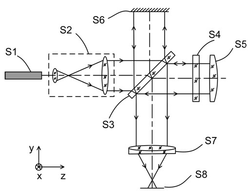
[0037] Examples of application of the present invention to partially compensated lens tilt alignment and decenter alignment are described below.

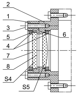
[0038] figure 1 It is a diagram of the partial compensation lens S5 tilt alignment device in the aspheric non-zero position interference detection. figure 2 for figure 1 The specific implementation of the combination and separation of the middle alignment plate S4 and part of the compensation lens S5: the alignment plate S4 and part of the compensation lens S5 are respectively placed in the mirror holders 1 and 2, and are fixed by the pressure ring 4; it can be realized by using the adjustment machine The alignment plate S4 and part of the compensating lens S5 are parallel to the respective reference planes 5 and 6 ; At this time, it can be realized physically that the alignment plate S4 is parallel to the part of the compensation lens S5.

[0039] figure 2 The middle auxiliary alignment plate S4 is a single parallel plate wit...


PUM


Abstract

The invention discloses an aligning device and an aligning method for a partial compensating lens during detection of aspheric surface and nonzero digit interference. The aligning device is characterized in that a fine light beam emitted by a laser is expanded by a collimating beam expanding system to form parallel broad light beams; after parallel light enters a beam splitter on which a part reflective semitransparent film is plated, one part of incident light is reflected and the reflected light beam is reflected by a plane reference mirror and then returns to the beam splitter again; the other part of incident light is transmitted and the transmitted light beam forwards spreads and enters an auxiliary aligning panel and then returns; the returned reflection light and the returned transmission light meet at the beam splitter to generate interference and form an interference pattern; the interference pattern passes through an imaging system and images at a detector; and the inclination of the aligning panel and the partial compensating lens, which are relative to the incident light, is adjusted, so that the detector obtains a zero-fringe interference pattern; and the inclined alignment of the partial compensating lens is realized by moving the aligning panel. According to the aligning device and the aligning method disclosed by the invention, the problem of aligning error of the partial compensating lens during detection of the aspheric surface and nonzero digit interference is solved and the adjustment error of the detection result caused by mistaken alignment is reduced.

Description

technical field [0001] The invention relates to a device and method for partially compensating lens alignment in aspheric surface non-zero position interference detection. Background technique [0002] In the aspheric surface non-zero interference detection, the partial compensation lens is responsible for compensating the longitudinal normal aberration of the aspheric surface within a certain range, reducing the slope of the return wavefront at the image plane of the system, and then making the interference fringes distinguishable by the detector. It is the core component of the whole non-zero interference system. In order to reduce the system error, it is required in principle that the partial compensation lens be correctly aligned (including tilt and decenter) with the non-zero interferometer, that is, its position in the actual system should be exactly the same as that in the theoretical model. If there is an alignment error, a large number of aberrations such as astigm...

Claims


Application Information

Patent Timeline
Patent Type & Authority Applications(China)
IPC IPC(8): G02B27/30G01B9/02
Inventor 杨甬英田超张磊韦涛
Owner ZHEJIANG UNIV
Why Eureka
Try Eureka