Energy-saving halogen lamp convenient to mount and dismount

A halogen bulb and halogen lamp technology, applied in the field of halogen lamps, can solve the problems of halogen bulb failure, waste of resources, and inability to arbitrarily choose different styles of outer bulbs, etc., to achieve the effects of protecting the environment, improving products, and saving resources

Inactive Publication Date: 2012-07-18
文德彪
View PDF4 Cites 2 Cited by
  • Summary
  • Abstract
  • Description
  • Claims
  • Application Information

AI Technical Summary

Problems solved by technology

The halogen bulb of this structure has the following disadvantages: (1) The failure of the halogen bulb will cause the halogen bulb to fail and be discarded. It is a waste of resources to discard the entire halogen bulb, because the lamp holder, ceramic or glass bulb, ceramic insulation The lamp holder can continue to be used normally; (2) Consumers cannot arbitrarily choose different styles of outer bulbs

Method used


Image

  • Energy-saving halogen lamp convenient to mount and dismount
  • Energy-saving halogen lamp convenient to mount and dismount
  • Energy-saving halogen lamp convenient to mount and dismount

Examples


Embodiment 1

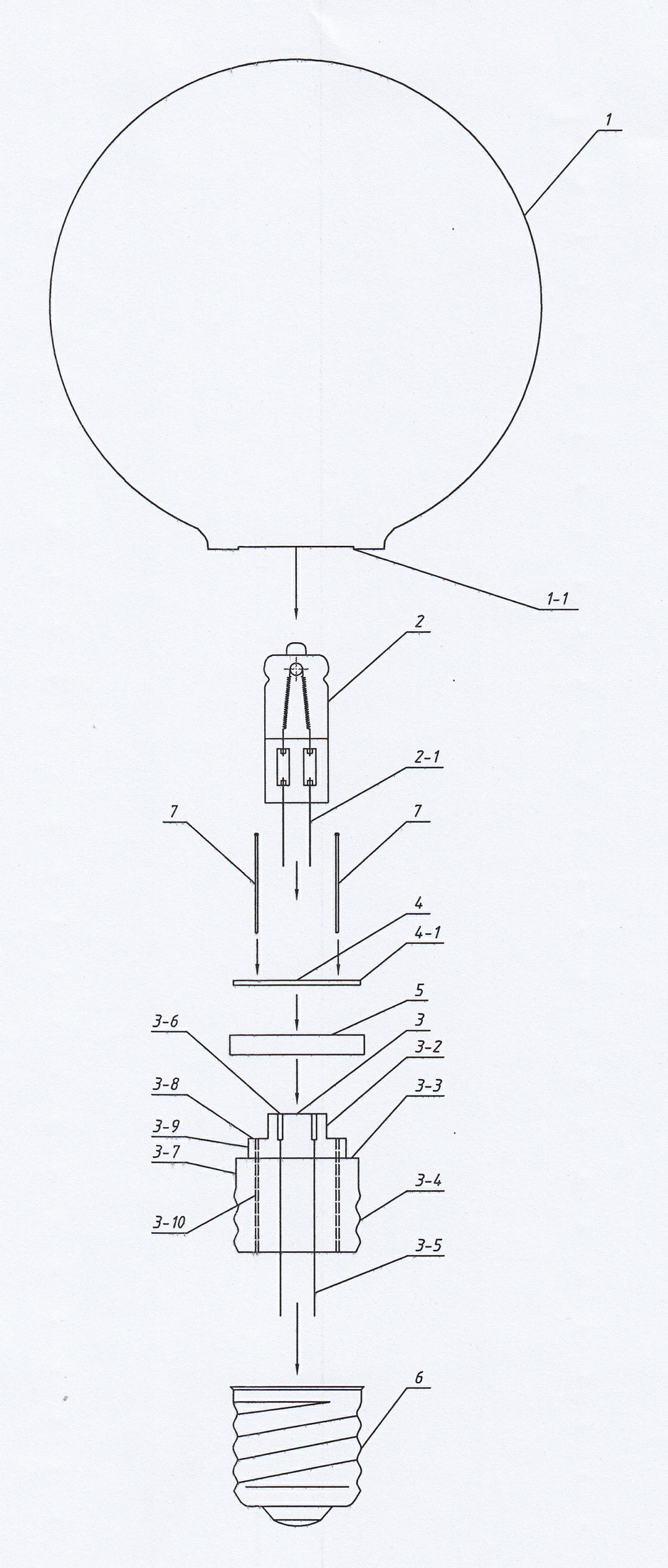
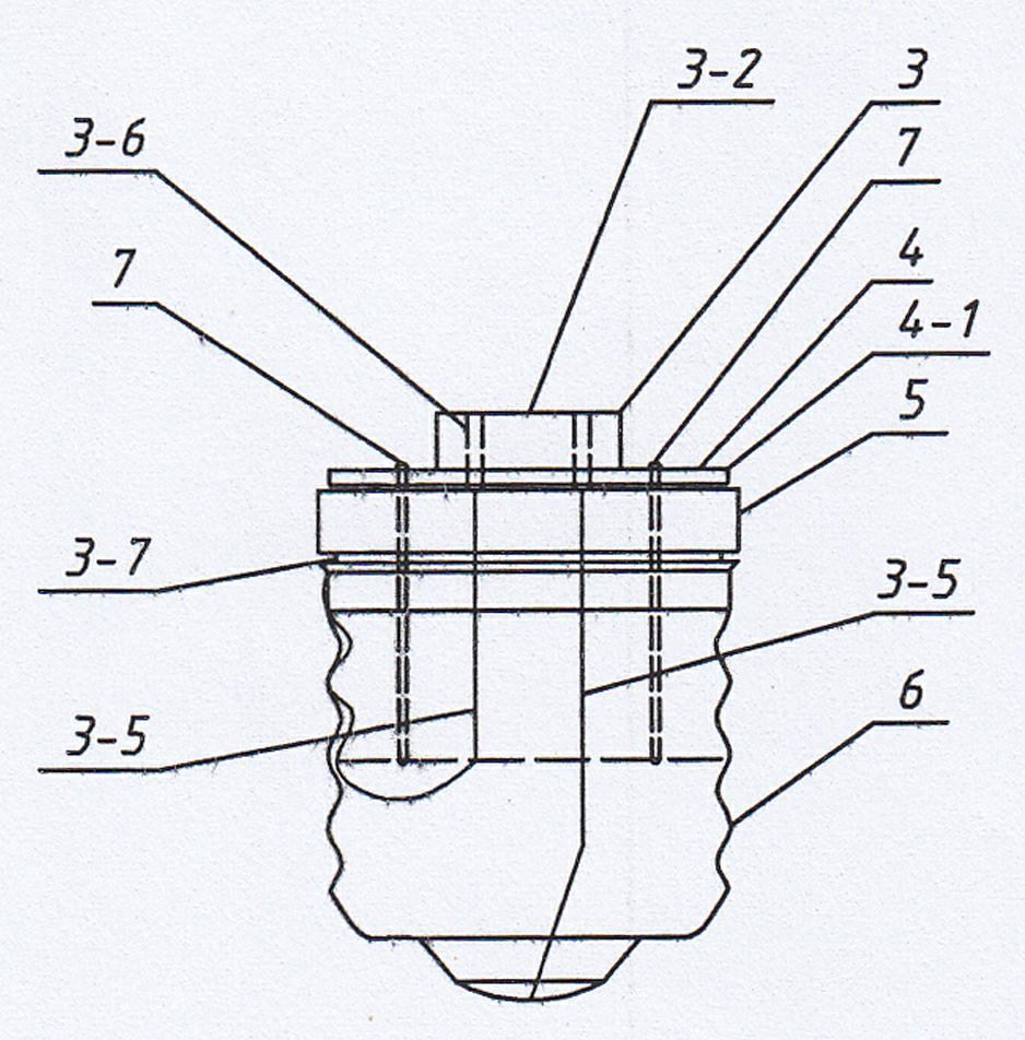
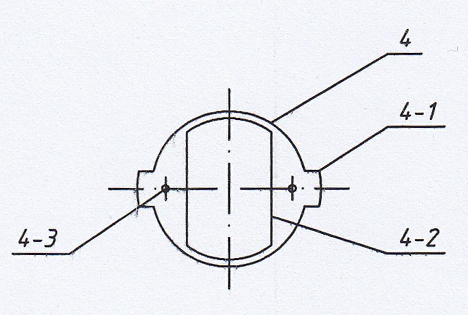
[0020] see Figure 1-Figure 5 As shown, an energy-saving halogen bulb that is easy to disassemble and assemble is composed of a thin ceramic outer bulb 1, a halogen lamp 2, a ceramic insulating lamp holder 3, a connecting snap ring 4, a soft elastic gasket 5, and a threaded lamp cap 6. A ceramic insulating lamp holder 3 is arranged in the E27 threaded lamp holder 6. The ceramic insulating lamp holder 3 is a three-stage cylinder with a small upper part and a larger lower part. The intersection of the small cylinder 3-2 and the middle cylinder 3-9 is the first limit Position platform 3-8, the intersection of middle cylinder 3-9 and large cylinder 3-7 is the second limit platform 3-3, and the outer cylinder of large cylinder 3-7 is provided with external thread 3-4, and positioning On the first limiting platform 3-8, the outer side of the metal connecting snap ring 4 is provided with two symmetrically arranged outer flanges 4-1, and the elastic soft gasket 5 is inserted into the ...

Embodiment 2

[0023] see Figure 6 As shown, the universal lamp cap 8 of the present embodiment adopts a B22d socket lamp cap, and the large cylinder of the ceramic insulated lamp holder 3 does not have an external thread, and the large cylinder matches the inner wall of the socket lamp cap 8, and the two are fixedly connected by an adhesive. The first electrode lead wires 3-5 respectively extend to the two mutually insulated and isolated electrodes at the center of the bottom end of the lamp cap 8, and are soldered firmly with tin wires, and the rest of the components and connection structure are the same as in Example 1.


PUM


Abstract

The invention discloses an energy-saving halogen lamp convenient to mount and dismount, wherein an insulating lamp holder is a three-level column body with a small upper part and a large lower part; the intersection part of a small column body and a middle cylindrical body is provided with a first spacing platform; the intersection part of the middle cylindrical body and the large column body is provided with a second spacing platform; a connecting clamping ring and an elastic flexible gasket are also arranged; the outer side of the connecting clamping ring is provided with at least two outer protruding edges which are distributed symmetrically; the elastic flexible gasket is sleeved on the middle cylindrical body and is placed on the second spacing platform; the connecting clamping ring is sleeved on the small column body and is fixedly connected to the first spacing platform through a rivet; the bottom of an outer lamp shell is provided with at least two openings which are matched with the outer protruding edges of the connecting clamping ring; and the openings of the lamp shell are clamped and fixed on the connecting clamping ring. The halogen lamp has the advantages that the invalid halogen lamp can be dismounted rapidly and is replaced with a new halogen lamp, and other components of the lamp are used continuously, thus not only is the environment protected, but also the resource waste is reduced, and the using cost is lowered greatly.

Description

technical field [0001] The invention relates to the technical field of halogen lamps, in particular to an energy-saving halogen bulb which is easy to assemble and disassemble. Background technique [0002] Currently widely used incandescent light bulbs have low luminous efficiency, the energy level standard can only reach below E level, and the working life usually can only reach about 1000 hours. Compared with the incandescent lamp, the halogen lamp with the same power can increase its light efficiency by 30%, and its service life can be doubled to 2000 hours. Incandescent bulbs are recognized as environmentally friendly bulbs. The light source is closest to natural light. Discarded incandescent lamps will not pollute the environment. In this respect, halogen lamps are very similar to incandescent lamps. By matching the halogen lamp with the lamp holder of the general incandescent bulb, such as E14, E17, E26, E27, B22d, etc., the halogen bulb can replace the general incand...

Claims


Application Information

Patent Timeline
Patent Type & Authority Applications(China)
IPC IPC(8): H01K1/36
CPCH01K1/34H01K1/46Y02B20/125H01K1/42Y02B20/00
Inventor 文德彪
Owner 文德彪
Why Eureka
Try Eureka