Rotor for rotary electric machine

A technology for rotating electrical machines and rotors, applied in electrical components, electromechanical devices, electrical components, etc., can solve the problems of reducing the forming dimensional accuracy and increasing the size of the pressing machine, increasing the manufacturing cost, and increasing the pressing load of the manufacturing end plate.

Inactive Publication Date: 2012-07-18
AISIN SEIKI KK
View PDF5 Cites 4 Cited by
  • Summary
  • Abstract
  • Description
  • Claims
  • Application Information

AI Technical Summary

Problems solved by technology

[0007] However, in the case of increasing the thickness of each end plate, the pressing load for producing the end plate also increases, which leads to a decrease in the molding dimensional accuracy and an enlargement of the press machine for producing the end plate
In addition, in this case, the durability of the stamping die forming the end plate decreases, thereby increasing the manufacturing cost due to the increased frequency of replacement of the stamping die

Method used


Image

  • Rotor for rotary electric machine
  • Rotor for rotary electric machine
  • Rotor for rotary electric machine

Examples


no. 1 example

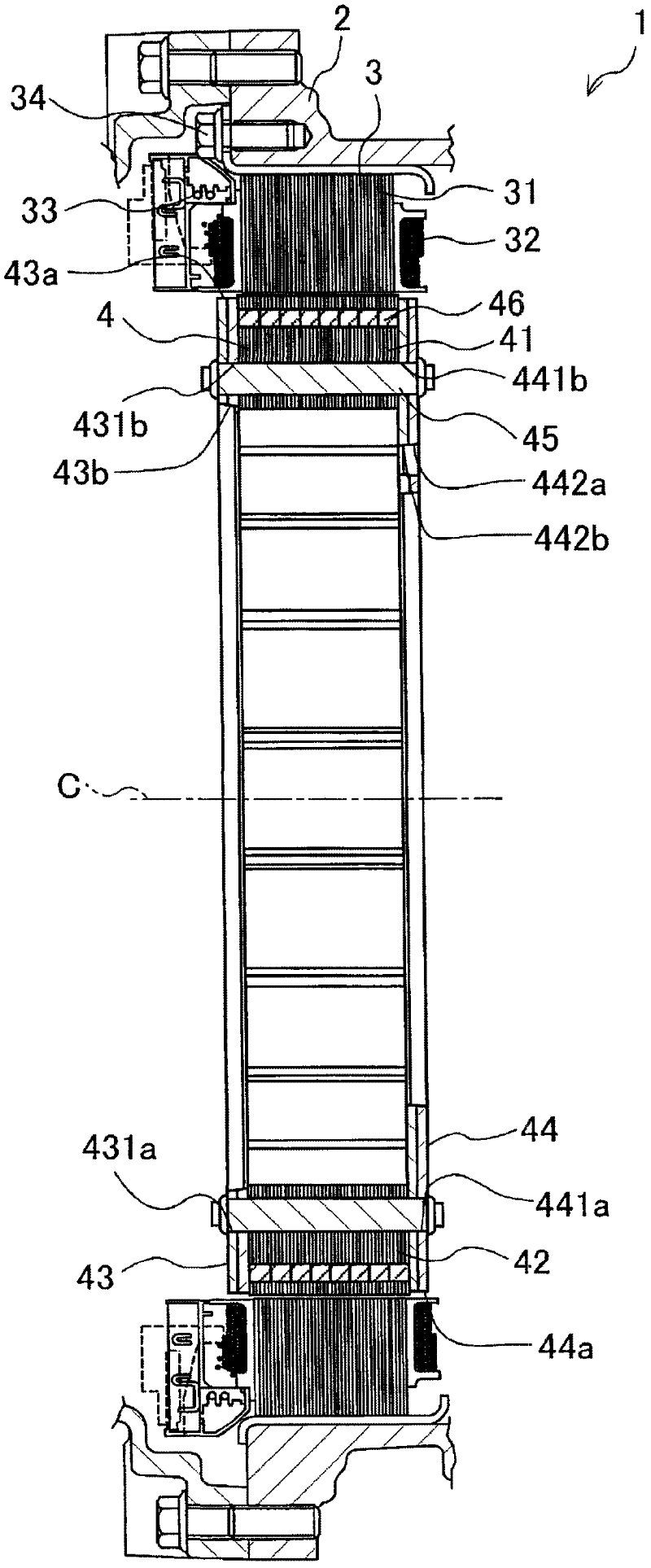
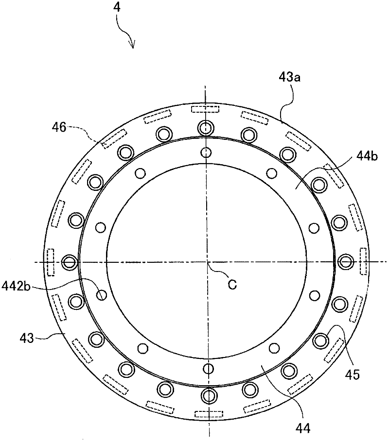
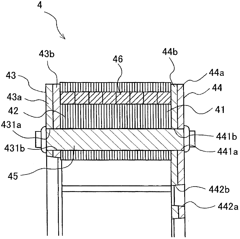
[0028] Below, refer to Figure 1 to Figure 5 , illustrates the rotor 4 of the motor 1 according to the first embodiment.

[0029] The electric motor 1 as the rotating electric machine according to the first embodiment is a synchronous electric motor for driving wheels of a hybrid vehicle. The electric motor 1 is arranged between a clutch device connected to the engine and a transmission. However, the motor 1 of the present embodiment can be applied to any type of motors, such as motors provided in home appliances, and motors driving industrial machines.

[0030] In the following description, unless otherwise specified, the direction of the rotation axis or the axial direction corresponds to the direction along the rotation axis C of the motor 1 (rotor 4), that is, figure 1 Middle left direction. in addition, figure 1 The left side in corresponds to the front side of the vehicle, while figure 1 The right side in corresponds to the rear side of the vehicle.

[0031] Such a...

no. 2 example

[0056] Below, refer to Figure 6 , illustrating the third end plate 47 as the second end plate according to the second embodiment. In the second embodiment, the same constituent elements or parts as those of the first embodiment are given the same reference numerals as those of the first embodiment, and descriptions thereof are omitted. refer to Figure 6 The third end plate 47 according to the second embodiment is explained. Such as Figure 6 As shown, the third end plate 47 of the rotor 4A includes a fifth constituent plate 47a as a third constituent member, and a sixth constituent plate 47b as a fourth constituent member. The fifth constituent plate 47a formed substantially in a ring shape includes twenty fifth holes 471a each being a through hole, and the fastening pins 45 are respectively inserted into the fifth holes 471a. In the same manner as the third constituent plate 44a of the first embodiment, fifth holes 471a are arranged at equal intervals in the circumferen...


PUM


Abstract

A rotor (4, 4A) for a rotary electric machine (1), the rotor being arranged to face a stator (3) and being roratably attached to a housing (2), the rotor includes a core body (41) formed by a plurality of core sheets (42) laminated in a direction of a rotational axis (C) of the rotor, first and second end plates (43,44,47) arranged at both end surfaces of the core body in a direction where the core sheets are laminated, and a fixing member (45) fixing the first and second end plates to the core body (41) to hold the core body by the first and second end plates, wherein at least one of the first and second end plates is formed by a plurality of composition members (43a, 43b, 44a, 44b, 47a, 47b) overlapping in a thickness direction of the first end plate and the second end plate.

Description

technical field [0001] The present invention generally relates to a rotor for a rotating electric machine. Background technique [0002] A known motor rotor is disclosed, for example, in JP11-98733A (hereinafter referred to as Patent Document 1). The rotor disclosed in Patent Document 1 includes a rotor core formed by laminating a plurality of magnetic steel plates, and sandwiching the rotor core with a pair of end plates in the lamination direction of the magnetic steel plates. A motor shaft including a protrusion at one axial end is passed through the rotor core and the end plate. Then, the retaining nut is fastened to the other axial end of the motor shaft, thereby retaining the rotor core with respect to the motor shaft by the pair of end plates. [0003] According to the motor rotor disclosed in Patent Document 1, annular steps are formed at the respective ends of the end plates. In addition, the coil wound around the stator core is bent radially outward. Therefore,...

Claims


Application Information

Patent Timeline
Patent Type & Authority Applications(China)
IPC IPC(8): H02K1/22
CPCH02K1/276
Inventor 朝贺崇杉山智也
Owner AISIN SEIKI KK
Why Eureka
Try Eureka