Speaker, and electronic apparatus and cellular phone using the speaker

A loudspeaker and terminal technology, applied in the field of loudspeakers, can solve problems such as the difficulty of thinning

Active Publication Date: 2012-07-18
PANASONIC CORP
View PDF5 Cites 2 Cited by
  • Summary
  • Abstract
  • Description
  • Claims
  • Application Information

AI Technical Summary

Problems solved by technology

Therefore, it is very difficult to realize thinning corresponding to market requirements

Method used


Image

  • Speaker, and electronic apparatus and cellular phone using the speaker
  • Speaker, and electronic apparatus and cellular phone using the speaker
  • Speaker, and electronic apparatus and cellular phone using the speaker

Examples


Embodiment approach 1

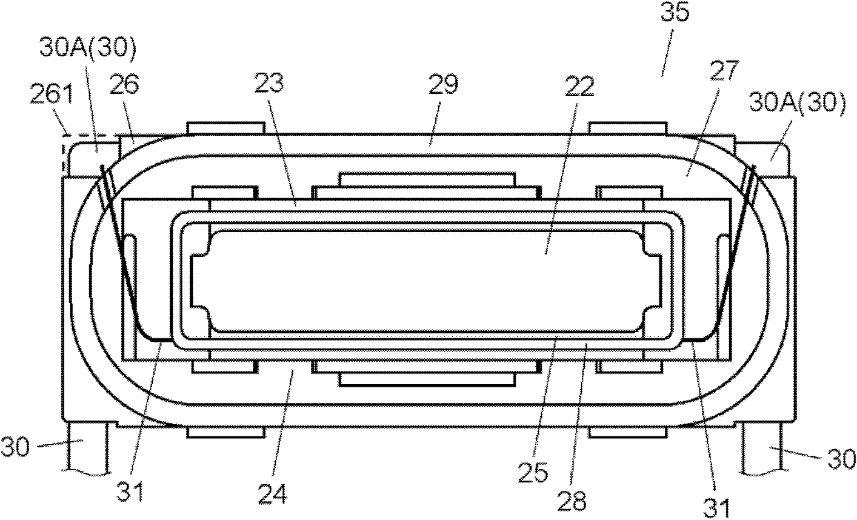
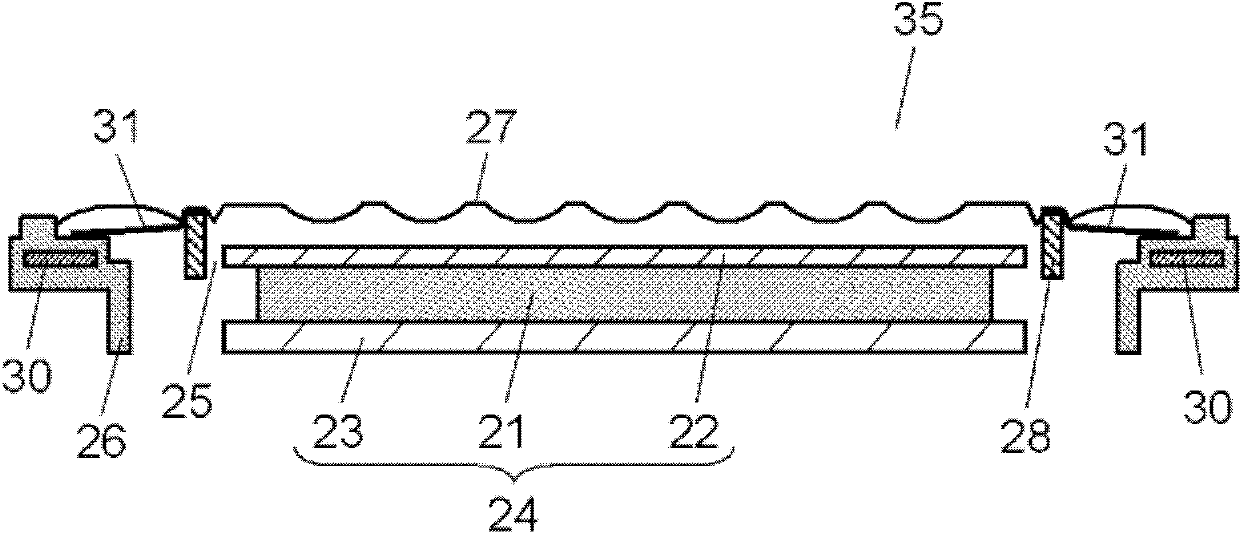
[0049] figure 1 , figure 2 It is a plan view and a cross-sectional view of the speaker according to Embodiment 1 of the present invention. The speaker 35 is a small speaker mounted on a portable electronic device such as a mobile phone. The speaker 35 includes a magnetic circuit 24 including a magnet 21 , a frame 26 , a diaphragm 27 , a voice coil 28 , and a terminal 30 . In addition, since the diaphragm 27 is made of a transparent material, it does not appear in a plan view, but the lower parts can be seen through the diaphragm 27 .

[0050] The inner magnetic type magnetic circuit 24 is formed by coupling the magnet 21 to the yoke 23 and coupling the upper plate 22 to the magnet 21 . The resin frame 26 is insert-molded with the yoke 23 and the terminal 30 . That is, the frame 26 is coupled to the magnetic circuit 24, and the terminal 30 is coupled to the frame 26 by insert molding.

[0051] The frame 26 has an opening 29 . The diaphragm 27 is bonded to the periphery ...

Embodiment approach 2

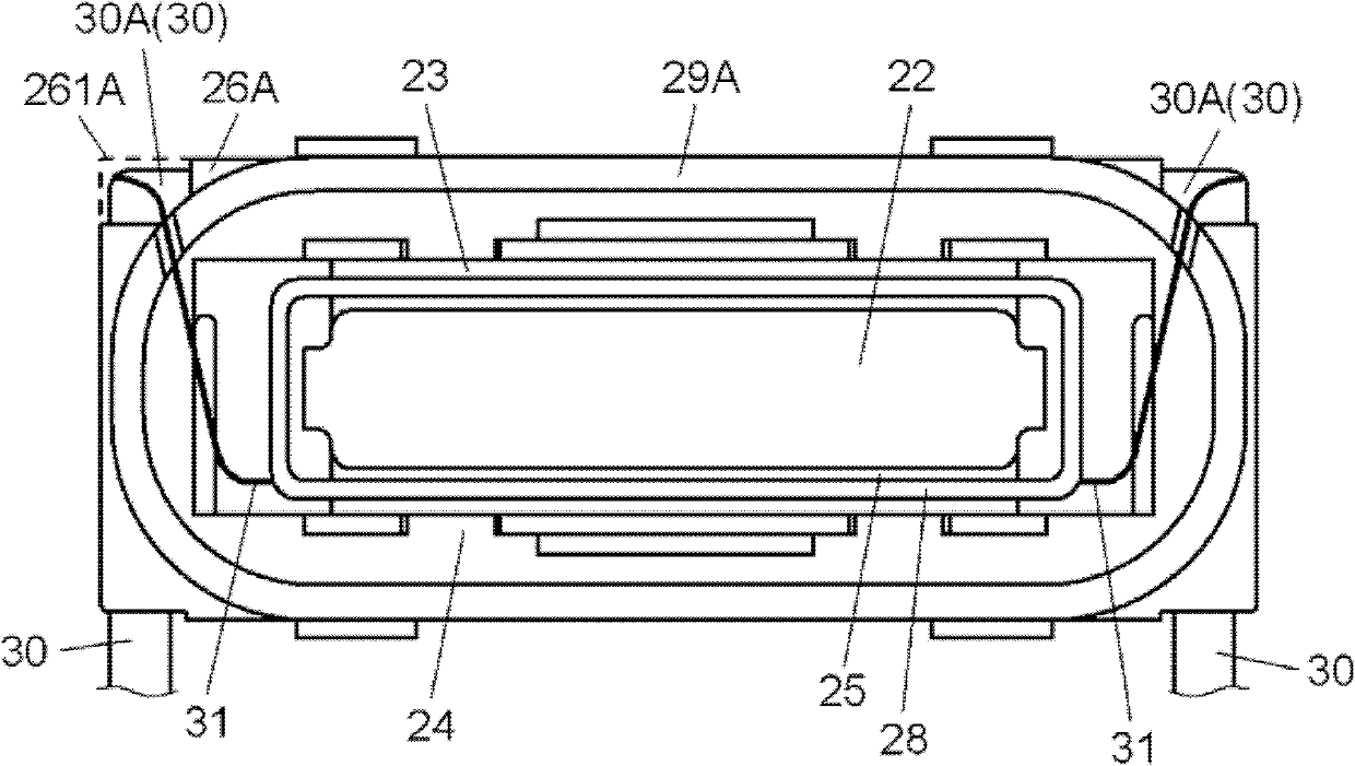
[0068] image 3 It is a plan view of the speaker in Embodiment 2 of the present invention in the middle of assembly, Figure 4 is a plan view of the loudspeaker in its finished state. Figure 5 is a cross-sectional view of the speaker.

[0069] The speaker 36 of the present embodiment differs from the speaker 35 of the first embodiment in that a frame composed of a first frame portion 26A and a second frame portion 26B is used instead of the frame 26 .

[0070] That is, the frame has a first frame portion 26A and a second frame portion 26B. The first frame portion 26A has a first opening portion 29A, and is coupled to the magnetic circuit 24 . The second frame portion 26B has a second opening portion 29B larger than the first opening portion 29A of the first frame portion 26A, and is joined to the first frame portion 26A. The outer shape of the second frame portion 26B is the same as or smaller than that of the speaker 36 . The diaphragm 27 is bonded to the periphery of t...

Embodiment approach 3

[0081] Next, refer to Figure 6 , Figure 7 An electronic device equipped with speaker 35 will be described. Figure 6 is a block diagram of a mobile phone that is an electronic device according to this embodiment, Figure 7 The sectional view of the main part of the mobile phone.

[0082] Such as Figure 6 As shown, the mobile phone 80 has speakers 35, 45, an input unit 50 for receiving input operations, a microphone 55, a display unit 60 made of liquid crystal, etc., and a circuit unit 40 having at least a function of driving the speaker 35.

[0083] That is, the circuit unit 40 receives an input from the input unit 50 , and displays the input, incoming call information, and the like on the display unit 60 . In addition, the circuit unit 40 receives voice input from the microphone 55 during a call, and reproduces the call from the communication address through the speaker 45 . In addition, the circuit unit 40 drives the speaker 35 to generate a ringing sound. The speak...


PUM


Abstract

Disclosed is a speaker having a magnetic circuit, a frame, a diaphragm, a voice coil, and a terminal. The frame has an opening, is connected to the magnetic circuit, and includes a resin portion. The diaphragm is connected to the circumferential edge of the opening of the frame. The voice coil has a lead line, is connected to the diaphragm, and has a part of the voice coil disposed in the magnetic gap of the magnetic circuit. The terminal is connected to the frame by means of insert molding. The outer shape configured by means of the frame and the terminal is rectangular or square, and chipped sections are provided at the corners of the outer shape of the resin portion of the frame. The terminal has a protruding portion that protrudes from each chipped section, and the lead line of the voice coil is connected to the protruding portion.

Description

technical field [0001] The present invention relates to a speaker used for various audio equipment, a mobile phone, and the like, and an electronic device and a mobile phone using the speaker. Background technique [0002] In recent years, the functions of portable electronic devices such as small audio equipment and mobile phones have been gradually enriched. In addition, further miniaturization, thinning, and compacting of equipment are required in the market for easier use and improved portability. Affected by such a market background, there is a demand for further miniaturization, thinning, and compacting of small speakers used in portable electronic devices in the market. [0003] However, reducing the area of ​​the diaphragm to meet demands for miniaturization, thinning, and compactness cannot be said to be a good development direction in view of the need to ensure the sound pressure level of the speaker. On the other hand, for compactness, it is very effective to mo...

Claims


Application Information

Patent Timeline
Patent Type & Authority Applications(China)
IPC IPC(8): H04R9/02H04R7/04H04R9/04
CPCH04R9/06H04R9/02H04R9/04H04R7/20H04R7/14H04R7/04H04R9/045H04R9/025H04R2499/11H04R31/00
Inventor 伊藤哲田名部毅彦久世光一川边昌志西本达哉
Owner PANASONIC CORP
Why Eureka
Try Eureka