Automatic wire feed straightening shaft of steel wire straightening cutting machine

A cutting machine and automatic threading technology, which is applied in the field of automatic threading and straightening shafts of steel wire straightening and cutting machines, can solve the problems of scratches, trouble, low work efficiency, etc., and achieve the effect of good quality

Inactive Publication Date: 2012-07-25
王文明
View PDF7 Cites 4 Cited by
  • Summary
  • Abstract
  • Description
  • Claims
  • Application Information

AI Technical Summary

Problems solved by technology

For example, the position of the straightening column on the straightening shaft against the steel wire is only in point contact, and the apex of the straightening column is likely to scratch the surface of the steel wire, so that the precision of the steel wire blank is not high; Each

Method used


Image

  • Automatic wire feed straightening shaft of steel wire straightening cutting machine
  • Automatic wire feed straightening shaft of steel wire straightening cutting machine
  • Automatic wire feed straightening shaft of steel wire straightening cutting machine

Examples


Embodiment Construction

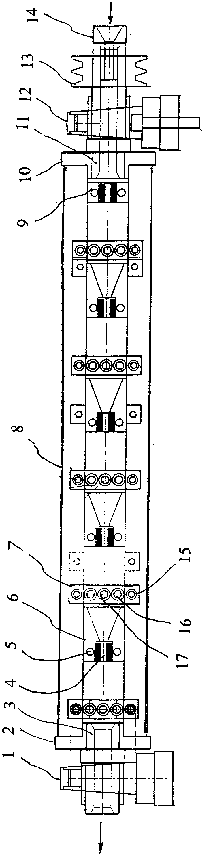
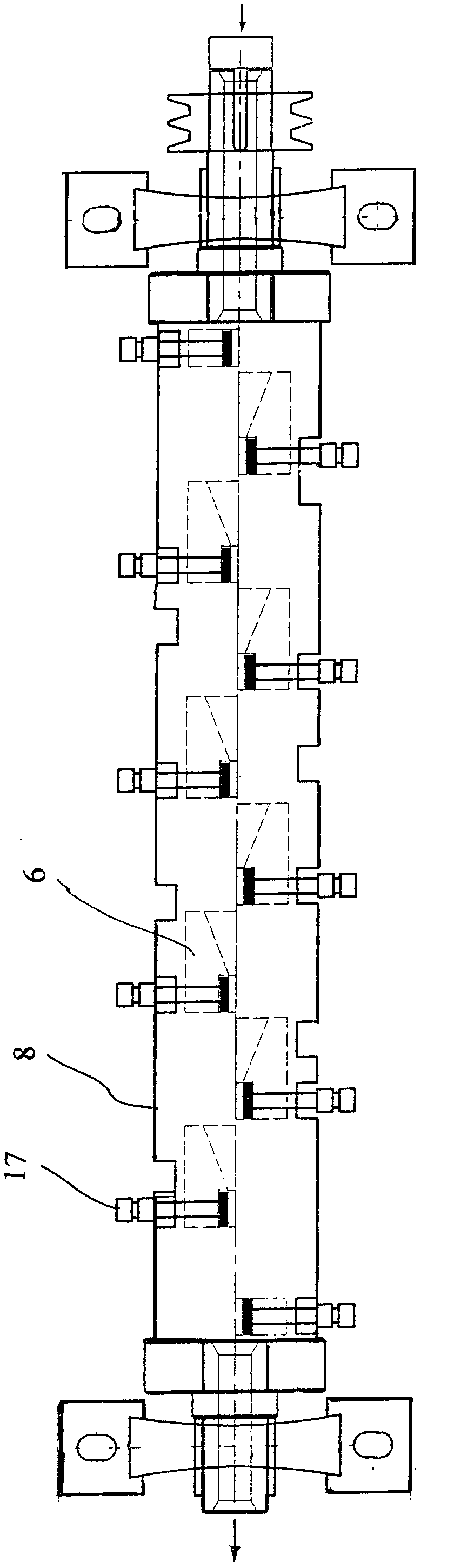
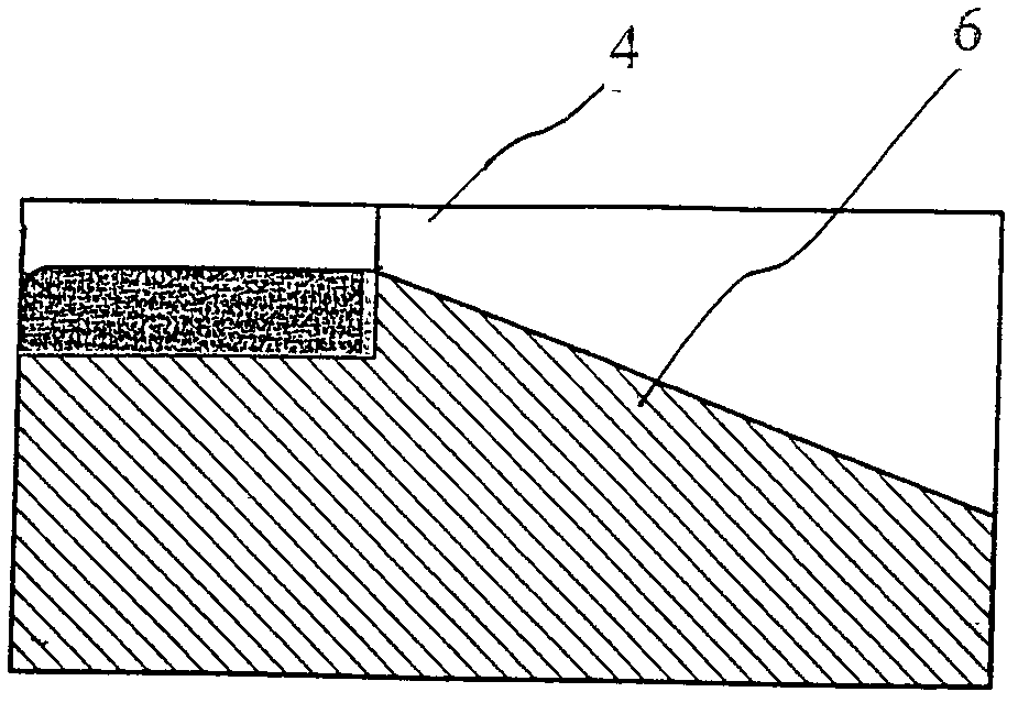
[0017] Such as Figure 1 to Figure 5 As shown, the present embodiment is an automatic wire threading straightening shaft of a steel wire straightening and cutting machine with a ten-level straightening die. The main body 8 is a hollow cylinder welded by two tile-shaped long strip plates with a half-moon shape. The main body 8 is axially provided with long grooves, and both ends are provided with hollow front and rear short shafts 11 / 3, which are mounted on the front and rear bearing blocks 12 / 1 of the fuselage. The front short shaft 11 of the feeding end of the straightening shaft is provided with a guide wire sleeve 14 in front of it, and several straightening modules 6 are arranged in the main body 8, and an adjusting plate 7 is arranged on the outer wall of the main body 8 corresponding to the straightening module 6, and each of the The straightening modules 6 are wedge-shaped and arranged at intervals on opposite sides of the inner wall of the straightening shaft. The str...


PUM


Abstract

The invention relates to an automatic wire feed straightening shaft of a steel wire straightening cutting machine. A body is a hollow cylindrical shell and is axially provided with an elongated groove. The two ends of the hollow cylindrical shell are disposed on a front bearing seat and a rear bearing seat of a frame. A belt pulley which is driven by a motor is disposed on a front short shaft. A plurality of straightening dies of wedge-shaped inclined faces are disposed in the inner cavity of the main body and are arranged on the inner walls of two opposite sides of the main body at intervals. The wedge-shaped inclined faces of the straightening dies face the steel wire feeding direction and semicircular straightening grooves are disposed on the inner sides of the rear portions of the dies. An oil-bearing copper layer is laid on each straightening groove. An adjusting plate provided with an adjusting bolt is arranged on an outer wall of the main body. The adjusting bolt is positioned and fixed by fixing screws after die gaps are finely adjusted. Due to the wedge-shaped inclined faces of the straightening dies, the automatic feeding of the steel wires is realized, and the steel wires can penetrate through the straightening grooves fast without manual traction. Due to the large contact area of the straightening groove and the oil-bearing copper layer, the straightened steel wires are fine in straightness without scratches on the surface. The straightening cutting machine is high is straightening precision and production efficiency.

Description

technical field [0001] The invention relates to a key component of a steel wire straightening and cutting machine, in particular to an automatic wire-threading and straightening shaft of a steel wire straightening and cutting machine that can quickly "top" the coiled steel wire. Background technique [0002] Enterprises that produce slender shafts or small hardware screws must use small-sized steel wires to cut off as blanks. First, the coiled steel wires of the entire coil must be loosely straightened before being straightened and cut. To complete this process, a wire straightening and cutting machine must be used, and the key component is the cylindrical straightening shaft. [0003] The applicant once invented a high-speed steel wire straightening and cutting machine tool. Although the work efficiency and straightening accuracy have been greatly improved compared with the existing steel wire straightening and cutting machine, there are still some shortcomings. For exampl...

Claims


Application Information

Patent Timeline
IPC IPC(8): B21F1/02
Inventor 王文明王旭斌
Owner 王文明
Why Eureka
Try Eureka