Blade for carrying out groove processing and cutting

A grooving and blade technology, which is applied to lathe cutting tools, metal processing equipment, turning equipment, etc., can solve problems such as flying out of the tool body, wear or chipping, and difficulty in complete contact between the upper and lower positioning surfaces, etc., to achieve Improve the ability to withstand cutting force and impact resistance, low manufacturing precision requirements, and increase the effect of positioning stability

Active Publication Date: 2012-07-25
ZHUZHOU CEMENTED CARBIDE CUTTING TOOLS CO LTD
View PDF5 Cites 1 Cited by
  • Summary
  • Abstract
  • Description
  • Claims
  • Application Information

AI Technical Summary

Problems solved by technology

In general, the grooving insert is a cemented carbide insert, which is often deformed during sintering. In addition, due to the existence of processing errors in the detection fixture, detection errors, and assembly errors with the cutting tool, the upper and lower positioning surfaces of the insert when assembled on the cutter body It is difficult to make full contact. At the same time, when the blade is clamped and during the cutting process, the upper and lower positioning surfaces of the blade are subjected to large and complex loads. It is difficult for the upper and lower positioning surfaces of the blade to fully contact with the positioning surface of the cutter body. During the cutting process, the upper and lower positioning surfaces of the insert and the positioning of the cutter body are basically in a state of edge line contact, or the cutter body is in contact with the protruding part of the insert deformation
The line contact between the blade and the cutter body generally occurs at the middle position and edge position of the upper and lower positioning surfaces. When the line contact is in the middle position of the blade, the blade will lose the positioning effect of the side direction. When the blade is cutting sideways, the blade will be clamped Unstable, fast wear or collapse; when the line contact is at the edge of the blade, the edge load of the upper and lower positioning surfaces of the blade is too large, and the wall thickness between the upper and lower positioning surfaces of the blade and the side is too small, and the shear stress of the upper and lower positioning faces of the blade is too large Large, it is very easy to cause the blade to be positioned up and down and face to the side.
When the blade is seriously deformed, the protruding parts of the upper and lower positioning surfaces play a positioning role, the blade is not clamped stably, and the blade is easy to break during cutting, and may even fly out of the cutter body

Method used


Image

  • Blade for carrying out groove processing and cutting
  • Blade for carrying out groove processing and cutting
  • Blade for carrying out groove processing and cutting

Examples


Embodiment Construction

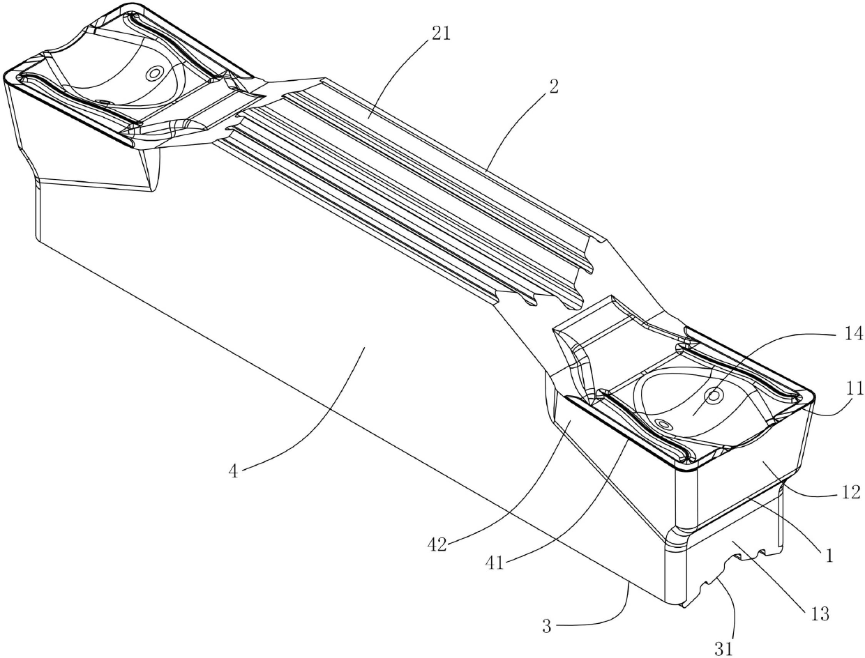
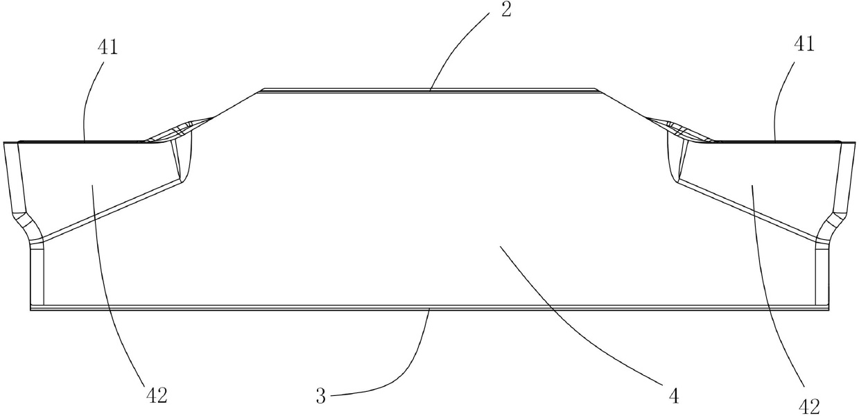
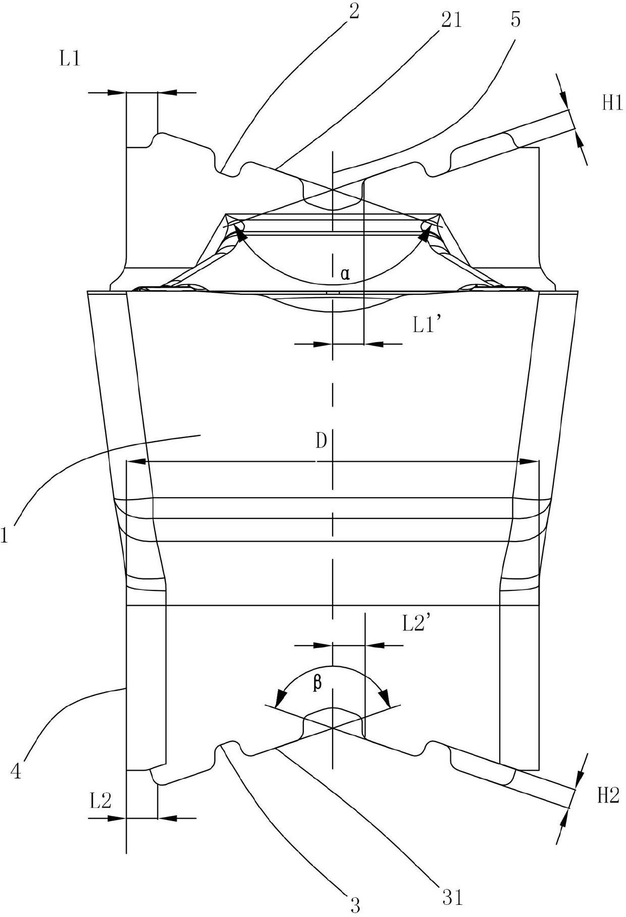
[0022] Figure 1 to Figure 4 It shows the first embodiment of the cutting insert for grooving of the present invention, which includes an upper positioning surface 2, a lower positioning surface 3, two side surfaces 4 and two end surfaces 1, and the two side surfaces 4 are connected to the upper positioning surface 2 and the lower positioning surface 3, the middle part of the upper positioning surface 2 and the lower positioning surface 3 is concave, and the cutting part of the insert is provided with a side edge 41, a side edge flank 42, an end edge 11, an end edge flank 12 and a chip guide groove 14 , the end face 1 is also provided with an end positioning surface 13, the structures at both ends of the blade are arranged symmetrically, the upper positioning surface 2 is provided with M discontinuous upper positioning platforms 21, and the lower positioning surface 3 is provided with N discontinuous lower positioning platforms. Positioning platform 31, 2≤M≤10, 2≤N≤10, M=N=4 i...


PUM


Abstract

The invention discloses a blade for carrying out groove processing and cutting, which comprises an upper positioning surface, a lower positioning surface, two end surfaces and two lateral sides. The lateral sides are connected with the upper positioning surface and the lower positioning surface; the upper positioning surface is provided with M discontinuous upper positioning tables; N discontinuous lower positioning tables are arranged on the lower positioning surface; wherein M is more than or equal to 2 and less than or equal to 10, and N is more than or equal to 2 and less than or equal to 10. With the adoption of the blade for carrying out groove processing and cutting, the positioning position and the angle can be automatically adjusted, the structure is stable, and the service life is long.

Description

technical field [0001] The invention relates to the field of metal cutting, in particular to a cutting blade for grooving. Background technique [0002] The positioning of the grooving blade in the up and down direction is realized by the upper and lower positioning surfaces of the blade. The upper and lower positioning surfaces of the blade are usually designed as a convex V-shaped surface or a concave V-shaped surface, which is designed to be a corresponding concave V-shaped positioning surface or The cutter body with convex V-shaped positioning surface is used to process various groove shapes. This kind of blade is easy to manufacture and easy to use. The positioning method of the contact between the convex V-shaped surface and the concave V-shaped surface increases the effective contact area of ​​the positioning surface of the blade, strengthens the ability of the blade to bear loads on the side and end faces, and improves the blade. The impact resistance and anti-crack...

Claims


Application Information

Patent Timeline
Patent Type & Authority Applications(China)
IPC IPC(8): B23B27/00
Inventor 刘敏江爱胜
Owner ZHUZHOU CEMENTED CARBIDE CUTTING TOOLS CO LTD
Why Eureka
Try Eureka