Numerical control paver for glass steel grid fiber

A glass fiber reinforced plastic and grid technology, which is applied in the field of CNC automatic fiber laying devices, can solve the problems of uneven product quality, low efficiency of glass fiber reinforced plastic grid, high labor cost, etc.

Inactive Publication Date: 2012-07-25
毛英旭
View PDF5 Cites 11 Cited by
  • Summary
  • Abstract
  • Description
  • Claims
  • Application Information

AI Technical Summary

Problems solved by technology

Due to the complete dependence on manpower, the production of FRP grating has problems such as low efficiency, uneven product quality, waste of raw materials, and high labor costs.

Method used


Image

  • Numerical control paver for glass steel grid fiber
  • Numerical control paver for glass steel grid fiber
  • Numerical control paver for glass steel grid fiber

Examples


Embodiment Construction

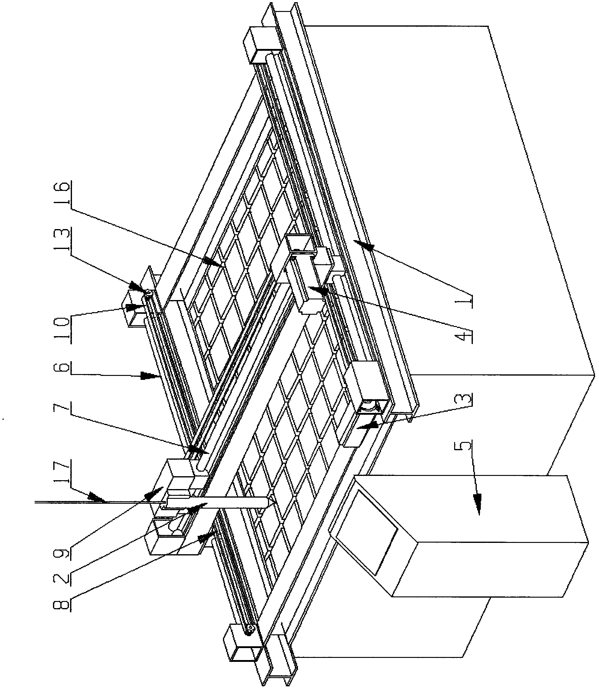
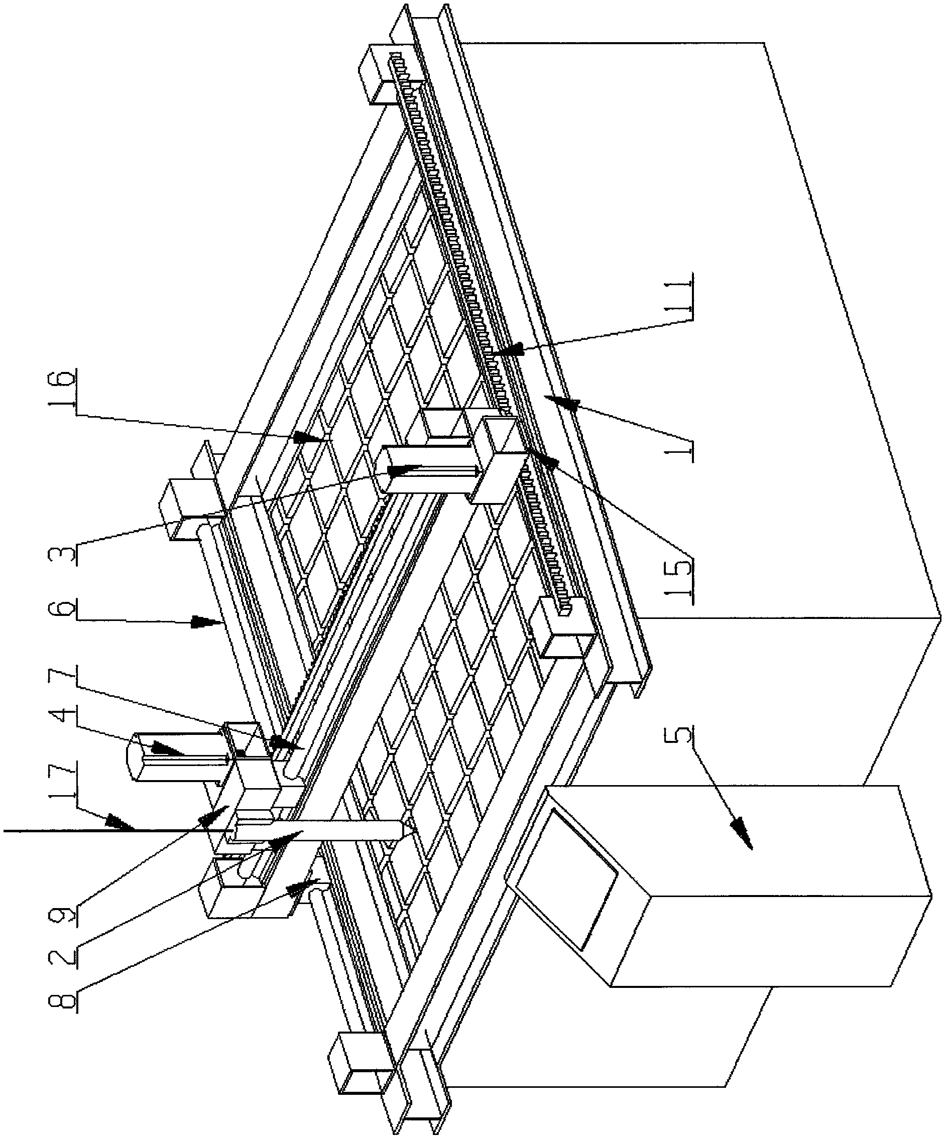
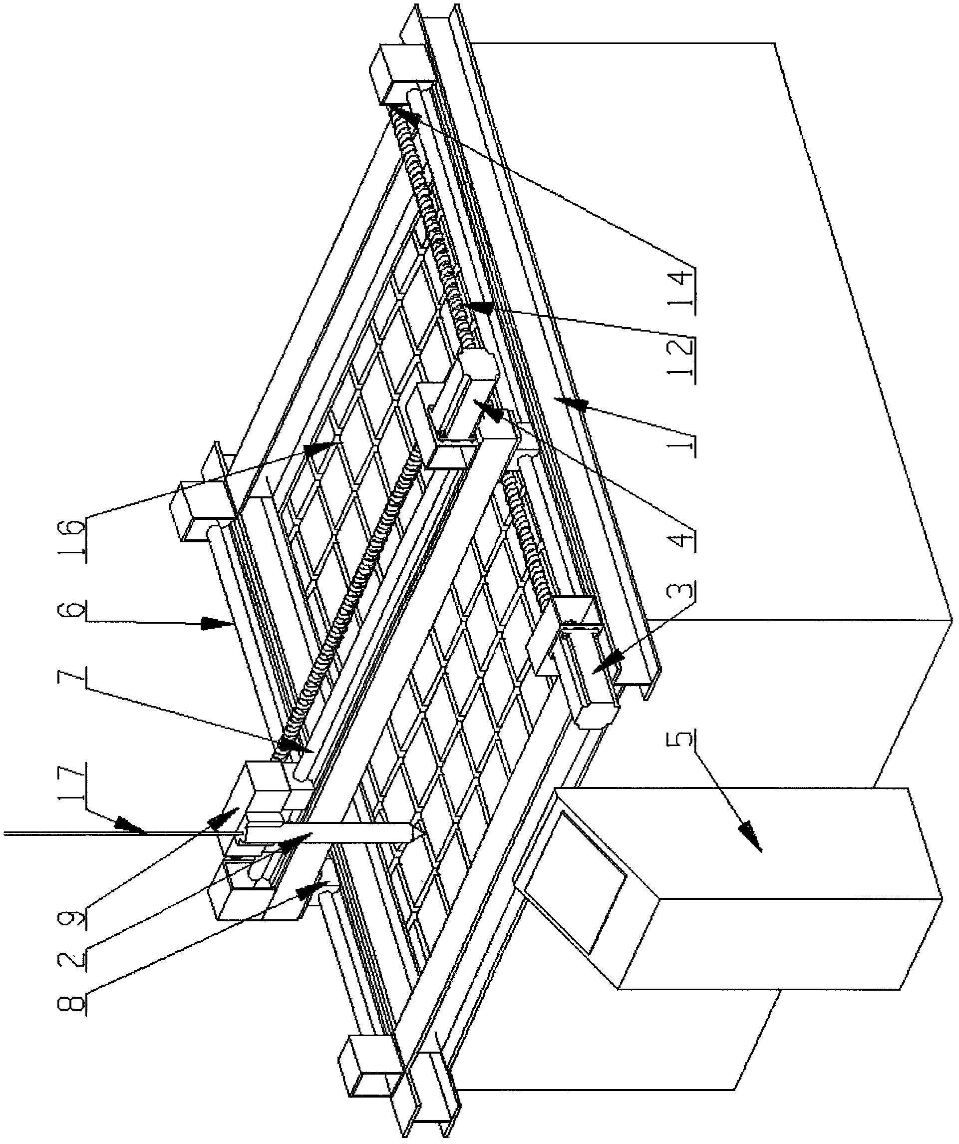
[0007] See attached figure 1 , 2 , 3. The present invention includes a main body frame (1), a fiber conduit (2), a high-speed servo motor (3) (4) and a special numerical control system (5). The main frame includes a Y-axis composed of two parallel guide rails (6) and an X-axis composed of a gantry-type guide rail (7) perpendicular to the Y-axis. Both ends of the X-axis use sliders (8) and Y-axis guide rails (6) ) are connected vertically. Another trolley (9) can slide along the axis on the X axis, and fiber conduit (2) is housed on it. There is a set of transmission systems on the Y axis and the X axis respectively, and a synchronous belt (10), a rack and pinion (11) or a screw mandrel (12) can be used according to the difference of fiber tension requirements. When using synchronous belt or screw drive, install a high-speed servo motor (3) at one end of the Y axis, and install a fixed synchronous wheel (13) or screw bearing (14) at the other end, and fix the opening of the ...


PUM


Abstract

The invention relates to the technical field of mechanical equipment, in particular to a numerical control automatic device for paving a fiber when a glass steel grid is produced. The invention aims at providing a numerical control automatic fiber paver which can complete liberate the expensive labor on a fiber paving link when the glass steel grid is produced, and is high in production efficiency, stable in product quality, and raw material-saving. The paver comprises a main frame, a fiber conduit, high-speed servo motors and a special numerical control system. The main frame comprises a Y-axis formed by two parallel guide rails and an X-axis formed by a gantry type guide rail, wherein the X-axis is further provided with a dolly which can slide along with the axial direction, and a fiber conduit is arranged on the dolly. A set of driving system is respectively arranged on the Y-axis and the X-axis. The main frame is fixed above a glass steel grid mould, and the two servo motors are connected with the special numerical control system. Only by inputting the relevant data such as the size and the like through the special numerical control system, the paver can be used for automatically paving the fiber, so that the production cost can be saved in many ways, and the product quality can be improved.

Description

technical field [0001] The invention relates to the technical field of mechanical equipment, in particular to a device for automatically laying fibers by numerical control in the production process of FRP gratings. Background technique [0002] At present, the fiber laying work in the production of FRP grating is purely manual operation, and the workers lay the fiber filaments into the FRP grating mold in a certain order. Due to the complete dependence on manpower, the production of FRP grating has problems such as low efficiency, uneven product quality, waste of raw materials, and high labor costs. Contents of the invention [0003] The purpose of the present invention is to provide a fiber numerical control automatic laying device that can completely liberate the expensive labor in the fiber laying link in the production of FRP grating, has high production efficiency, stable product quality, and saves raw materials. [0004] The technical scheme of the present invention...

Claims


Application Information

Patent Timeline
Patent Type & Authority Applications(China)
IPC IPC(8): B29C70/38
Inventor 毛英旭
Owner 毛英旭
Why Eureka
Try Eureka