Digital Rudder Angle Indication System

A rudder angle indicator and rudder angle technology, which is applied to steering and steering with rudder, can solve the problems of limited interface, asymmetric display, short mechanical life, etc. Effect

Inactive Publication Date: 2016-12-14
SHANGHAI SIMIFU INDAL
View PDF8 Cites 0 Cited by
  • Summary
  • Abstract
  • Description
  • Claims
  • Application Information

AI Technical Summary

Problems solved by technology

[0003] 1. The mechanical structure in this scheme is relatively complex, there is a cumulative error in the rudder angle value, and it cannot be corrected, and the repetition accuracy is low, usually ±1°
[0004] 2. The core device in the system adopts the self-aligning machine, so the mechanical life is short
[0005] 3. The system has high requirements on the parallelogram connecting rod structure installed in the steering gear cabin, so in the project, the construction is difficult
[0006] 4. Due to the particularity of the application field, the repeater unit is required to display from left 45° to right 45°. When the traditional three-sided rudder angle indicator converts the analog value into a mechanical angle, the relationship between the two is not completely linear, so there is show asymmetrical problems
[0007] 5. Since the system composed of the self-aligning mechanism is driven by one sending mechanism and multiple receiving mechanisms at the same time, the display value of the receiving mechanism installed in the repeater unit will have deviations, and the debugging for this problem is also very complicated.
[0008] 6. The data transmission in this system adopts analog quantity, so the interface provided to other equipment is limited, and there is no external digital interface
[0009] 7. In addition, the system also has disadvantages such as high cost and high noise

Method used


Image

  • Digital Rudder Angle Indication System
  • Digital Rudder Angle Indication System
  • Digital Rudder Angle Indication System

Examples


Embodiment Construction

[0043] In order to make the technical means, creative features, goals and effects achieved by the present invention easy to understand, the present invention will be further described below in conjunction with specific illustrations.

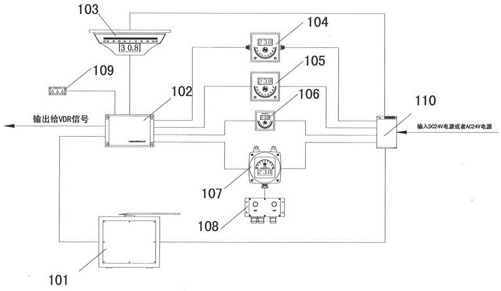
[0044] The digital rudder angle indicating system described in the present invention can be regarded as a purely digital rudder angle indicating system in the true sense. According to the actual application environment, the system provides rudder angle indicators with different protection levels (up to IP56 protection level) and different installation methods.

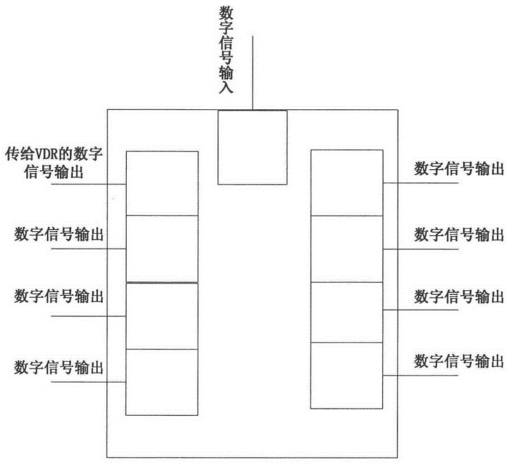
[0045] like figure 1 As shown, the main structure of the system includes a rudder angle transmitter 101, a signal distributor 102, and several rudder angle indicators that adopt digital signal transmission and digital display. These rudder angle indicators include three-sided rudder angle indicators 103, wall-mounted single-sided rudder angle indicators 104, embedded single-sided rudder...


PUM


Abstract

The invention discloses a digital rudder angle indicating system. Including the rudder angle transmitter used to convert the analog signal into a digital signal; the signal distributor connected to the rudder angle transmitter to receive the digital signal; the three-sided rudder angle indicator connected to the signal distributor to receive the digital signal; the connection signal distribution Waterproof single-sided rudder angle indicator; and at least one single-sided rudder angle indicator; outside the rudder angle transmitter, there is a connecting rod connected to the rudder blade, and a sampling potentiometer and rudder angle signal processing are installed inside. board; the rudder angle signal processing board includes a main control chip, and a display unit, a calibration button, a program burning module, a digital signal sending module and a power interface module respectively connected to the main control chip; the sampling potentiometer is connected to the rudder blade through Driven by the connecting rod, the analog signal is transmitted to the main control chip to be processed into a digital signal, and these digital signals are displayed on the display unit, and then transmitted to the signal distributor by the digital signal sending module.

Description

Technical field: [0001] The invention relates to ship instruments and equipment, in particular to a digital rudder angle indicating system. Background technique: [0002] The existing rudder angle indication system mainly transmits the rudder angle position signal through the parallelogram mechanism to transmit the mechanical angle of the actual position of the rudder blade to the receiver of the repeater unit through the auto-adjuster, and then drives the pointer through the gear, so that in the repeater unit Read the current rudder angle value on the dial, this method has the following disadvantages: [0003] 1. The mechanical structure in this scheme is relatively complex, there is a cumulative error in the rudder angle value, and it cannot be corrected, and the repetition accuracy is low, usually ±1°. [0004] 2. The core device in the system adopts a self-aligning machine, so the mechanical life is short. [0005] 3. The system has high requirements on the parallelogr...

Claims


Application Information

Patent Timeline
Patent Type & Authority Patents(China)
IPC IPC(8): B63H25/36
Inventor 闵刚胡建中黄建祥徐明根尹国龙
Owner SHANGHAI SIMIFU INDAL
Why Eureka
Try Eureka