Positioning fixture for steel rail drilling

A technology for positioning fixtures and rails, which is applied in the direction of track, track laying, track maintenance, etc. It can solve the problems of complicated drilling procedures and low processing efficiency, and achieve the effects of convenient clamping, improved processing efficiency, and simple drilling procedures

Inactive Publication Date: 2012-07-25
永煤集团股份有限公司新桥煤矿
View PDF4 Cites 5 Cited by
  • Summary
  • Abstract
  • Description
  • Claims
  • Application Information

AI Technical Summary

Problems solved by technology

[0003] The object of the present invention is to provide a rail drilling positioning jig to solve the problems of complicated drilling procedures and low processing efficiency in the prior art

Method used


Image

  • Positioning fixture for steel rail drilling
  • Positioning fixture for steel rail drilling
  • Positioning fixture for steel rail drilling

Examples


Embodiment Construction

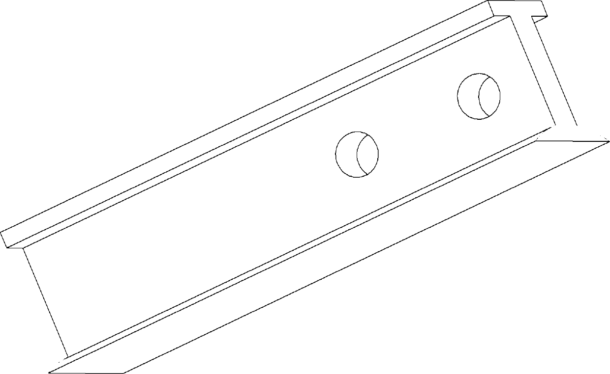
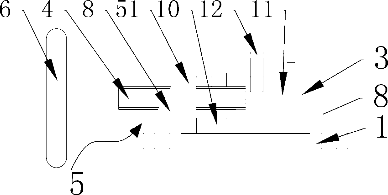
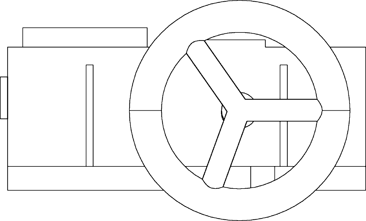
[0025] An embodiment of a rail drilling positioning fixture, such as Figure 1-3 As shown, it includes a base plate 1 for placing rails. The four corners of the base plate 1 are provided with U-shaped notches 9 for fixed connection with drill press screws, and the upper surface of the base plate 1 is provided with clamps for clamping the rails from both sides. mechanism, the clamping mechanism includes a fixed clamping block 3 which is welded and fixedly arranged on one side of the upper surface of the bottom plate 1 perpendicular to the bottom plate, a movable clamping block 4 which is set on the other side of the upper surface of the bottom plate 1, and a movable clamping block for driving The clamping block 4 moves toward and away from the fixed clamping block 3 to increase or decrease the distance between the two clamping blocks to loosen or clamp the driving mechanism 5 of the rail. The fixed clamping block 3 There are reinforcing ribs 8 welded between the outer side and ...


PUM


Abstract

The invention discloses a positioning fixture for steel rail drilling, which comprises a bottom plate for holding a steel rail. A clamping mechanism for clamping the steel rail from two sides is disposed on the upper surface of the bottom plate and comprises two opposing clamping blocks disposed on two sides and a driving mechanism. The driving mechanism is used for increasing or decreasing the distance between the two clamping blocks to loose or clamp the steel rail. A fixed positioning block for positioning the steel rail in drilling is disposed at the front end of the bottom plate. A flat plate parallel to the bottom plate is disposed at the upper end of every clamping block. The flat plate is provided with a bit positioning hole which axially and perpendicularly penetrates through a center line of the bottom of the steel rail which is clamped. After the fixture is fixed on a drilling machine and the steel rail is clamped, the bit can be aligned with the positioning hole for drilling, and punching the steel rail, removing a positioning device and moving the steel rail to the drilling machine to drill the steel rail in the prior art is not required. The drilling process using the fixture is simple, and the efficiency of machining the steel rails is improved greatly.

Description

technical field [0001] The invention relates to a fixture for positioning the rail when the rail is drilled. Background technique [0002] When installing and replacing rails, it is necessary to drill holes in the rails to connect the rails together, as shown in the attached figure 1 As shown, two connecting holes are drilled on the rail bottom of the cylinder rail along the center line of the rail bottom of the rail at one end of the rail. The locator of the rail drilling in the prior art is 93217883.9 as the Chinese patent authorization announcement number, authorized The date of announcement is July 13, 1994, and the name is "Rail Drilling Locator". A rail drilling locator is disclosed in the specification, which includes a sample plate that is closely attached between the two side plates of the rail. The outer side of the sample plate is fixed with a guide sleeve at the plate hole, and a steel sleeve is arranged inside the guide sleeve, and a punch is inserted in the st...

Claims


Application Information

Patent Timeline
Patent Type & Authority Applications(China)
IPC IPC(8): E01B31/06
Inventor 余林凯孙傲成王伟鹏
Owner 永煤集团股份有限公司新桥煤矿
Why Eureka
Try Eureka