Backlight module and liquid crystal display device using the backlight module

A backlight module and backplane technology, which is applied in the direction of lighting devices, fixed lighting devices, lighting device components, etc., can solve the problems of inappropriateness, high cost of elastic metal sheets, and small deformation of optical diaphragms, etc., and achieve reduction Probability of bending deformation, increased brightness, and easy installation

Inactive Publication Date: 2012-07-25
TCL CHINA STAR OPTOELECTRONICS TECH CO LTD
View PDF4 Cites 13 Cited by
  • Summary
  • Abstract
  • Description
  • Claims
  • Application Information

AI Technical Summary

Problems solved by technology

However, the above two positioning methods have not solved the positioning of the optical film in the vertical direction of the optical film plane, which may cause the warping of the optical film. Usually, small-sized backlight modules can use adhesive tape due to the small deformation of the optical film. Paste the optical film on the plastic frame, but the adhesive tape method is not sui

Method used


Image

  • Backlight module and liquid crystal display device using the backlight module
  • Backlight module and liquid crystal display device using the backlight module
  • Backlight module and liquid crystal display device using the backlight module

Examples


Example Embodiment

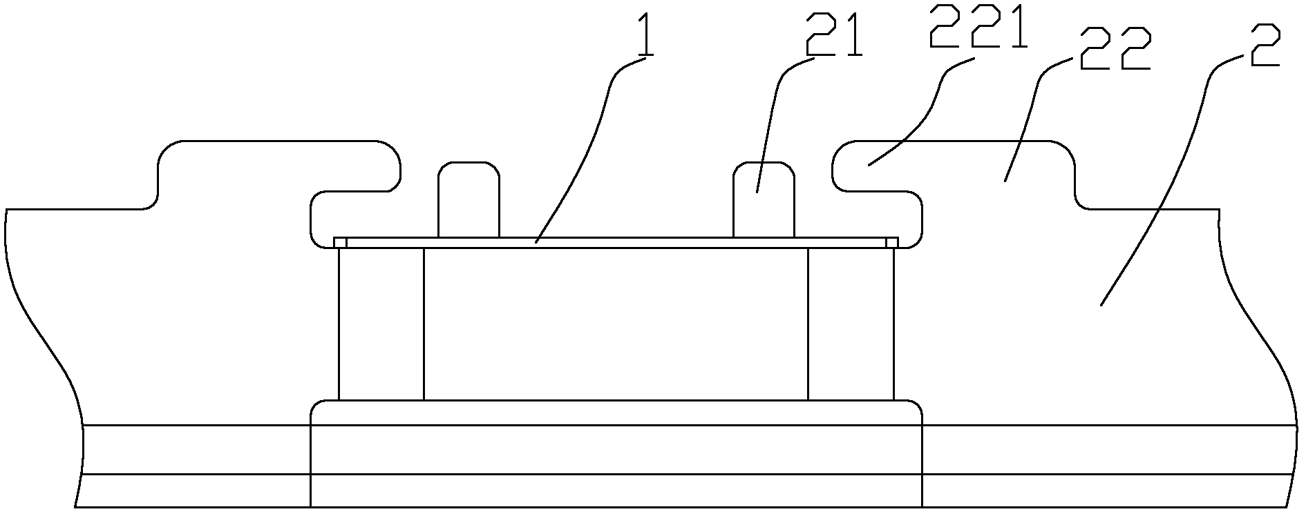
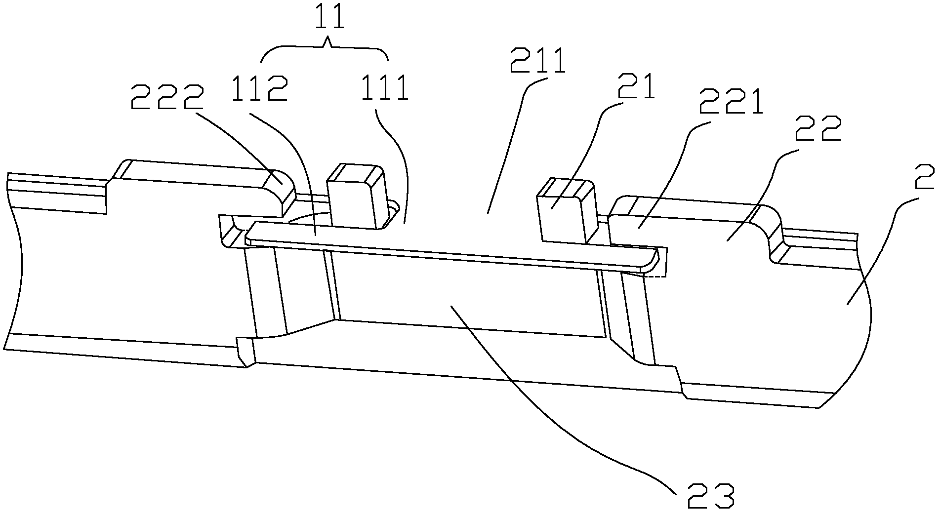
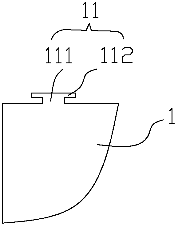
[0023] The invention discloses a liquid crystal display device comprising a backlight module, as an embodiment of the backlight module of the invention, such as Figure 1 to 3 As shown, the backlight module includes a back plate 2 and an optical film 1 arranged on the back plate 2. The optical film 1 is provided with a lug 11 for positioning, and the lug 11 has a portion 111 and a direction An expanded portion 112 extending outward, the width of the expanded portion 112 is greater than the width of the root 111, a first protrusion 21 is provided on the side wall of the back plate 2, and an opening 211 is provided on the first protrusion 21, The root 111 of the lug 11 of the optical film 1 is accommodated in the opening 211, the side wall of the back plate 2 is further provided with a second protrusion 22, and the second protrusion 22 has an extension 221, The expanded portion 112 of the lug 11 of the optical film 1 is accommodated under the extension portion 221 of the second p...


PUM


Abstract

The invention relates to a backlight module and a liquid crystal display device using the backlight module. The backlight module includes a back plate and an optical film arranged on the back plate, wherein a lug for location is arranged on the optical film, and includes a root part and an expansion part extending outwards; the width of the expansion part is larger than that of the root part; a first bump is arranged on the sidewall of the back plate; an opening is formed on the first bump; the root part of the lug of the optical film is accommodated in the opening; a second bump is arranged on the sidewall of the back plate and includes an extension part; and the expansion part of the lug of the optical film is accommodated below the extension part of the second bump. By arranging the second bump on the back plate, the extension part of the second bump can prevent the lug of the optical film from moving in a direction vertical to the plane of the optical film; the second bump can be arranged at a low cost; and the optical film is simple in installation and can save time and effort.

Description

technical field [0001] The invention relates to the field of liquid crystal display, more specifically, to a backlight module and a liquid crystal display device using the backlight module. Background technique [0002] Liquid crystal display devices need to use backlight modules and liquid crystal panels. Some optical films need to be used in the backlight modules. Such optical films can play the role of fogging and brightening. , it is necessary to position the above-mentioned optical film. For example, the patent No. 200410091576.X, the Chinese invention patent titled the combined structure of the optical film and the plastic frame mentions various positioning structures. The optical film in the prior art They are all positioned on the plastic frame. Because the optical film is generally thin, about 0.1-0.6mm, small and medium-sized backlight modules generally adopt leaning positioning, but in large-sized backlight modules, due to the relatively small size of the optical ...

Claims


Application Information

Patent Timeline
IPC IPC(8): F21S8/00F21V17/10G02F1/13357
CPCG02F2201/465G02F2001/133322F21V17/10G02F1/133608F21S8/00G02F1/133322
Inventor 唐国富
Owner TCL CHINA STAR OPTOELECTRONICS TECH CO LTD
Why Eureka
Try Eureka