Geometrical variable flame stabilizing device

A flame stabilization and variable technology, applied in combustion methods, combustion chambers, combustion equipment, etc., can solve the problems of unable to maintain flame stabilization performance and flow resistance loss, unable to optimize combustion flame stabilization performance and flow resistance loss, etc. Less, more achievable and simple in structure

Inactive Publication Date: 2012-07-25
BEIHANG UNIV
View PDF5 Cites 20 Cited by
  • Summary
  • Abstract
  • Description
  • Claims
  • Application Information

AI Technical Summary

Problems solved by technology

[0008] The purpose of the present invention is to solve the problem that the flame stabilizing device with a fixed geometric structure in the existing afterburner flame stabilizing technology cannot maintain the optimal combustion flame stabilizing performance and flow resistance loss under different working conditions, and proposes a geometrically adjustable Variable Flame Stabilizer
[0009] In the existing afterburner flame stabilization technology, the blunt body flame stabilization device with fixed geometry cannot maintain the optimal flame stabilization performance and flow resistance loss under different working conditions. The present invention proposes a geometrically variable flame stabilization device. device, by changing the geometric structure of the stabilizing device to solve the above technical problems

Method used


Image

  • Geometrical variable flame stabilizing device
  • Geometrical variable flame stabilizing device
  • Geometrical variable flame stabilizing device

Examples


Embodiment Construction

[0028] The present invention will be further described in detail below with reference to the accompanying drawings and embodiments.

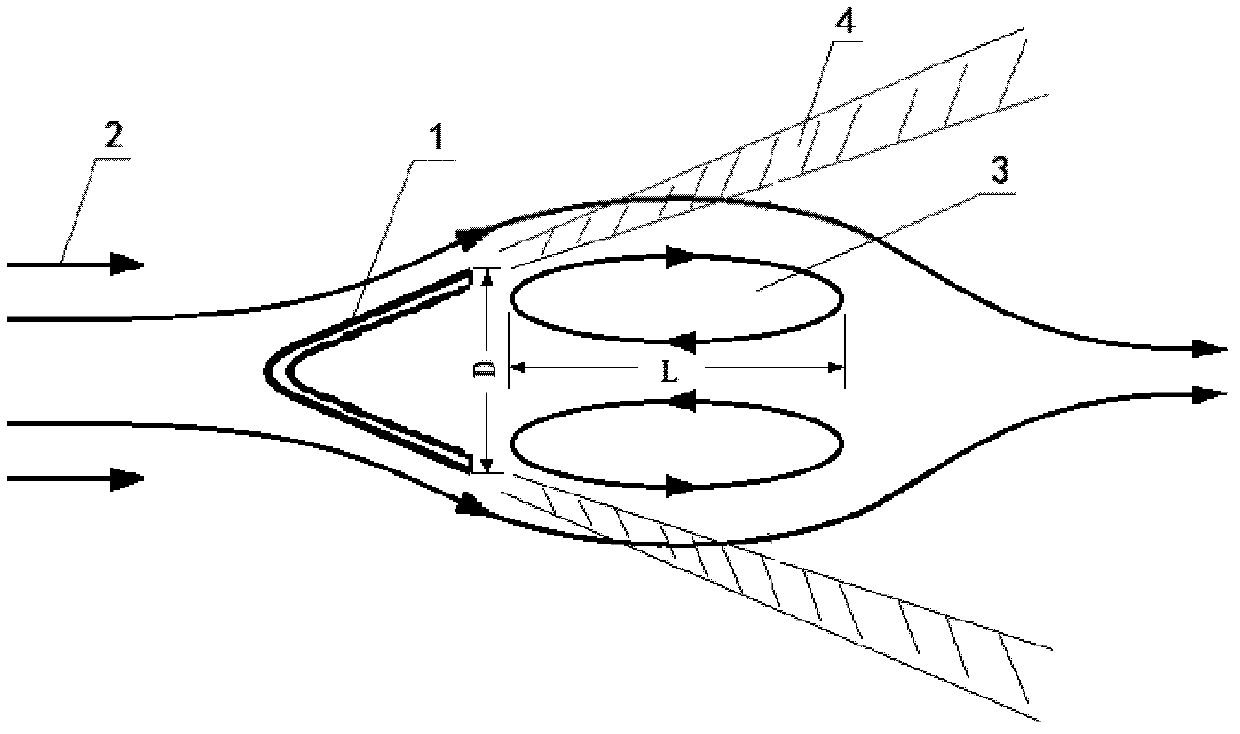
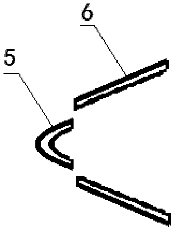
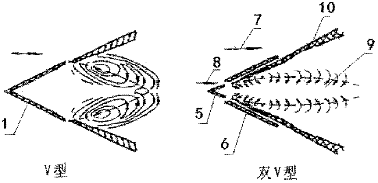
[0029] The geometric variable flame stabilization device provided by the present invention, such as Figure 4 , Figure 5 shown, specifically:

[0030] The geometrically variable flame stabilization device provided by the present invention takes a V-shape as a basic bluff body structure, and is composed of a stabilizer main body part and a transmission power part. The main part of the stabilizer is as Figure 4 As shown, it includes a front streamlined head 11, a rear movable blade A12 with a rotating shaft 16A, a rear movable blade B13 with a rotating shaft 17B, a rotating shaft support plate 14 and a mounting seat 15. Both ends of the streamlined head 11 are fixedly connected to the mounting seat 15. and the shaft support plate 14. The two ends of the rotating shaft A16 and the rotating shaft B17 respectively pass through the mounting hole...


PUM


Abstract

The invention discloses a geometrical variable flame stabilizing device and belongs to the technical field of afterburner flame stabilization of aircraft engines. The geometrical variable flame stabilizing device disclosed by the invention utilizes a V-shape as a basic bluff body structure and consists of a main body part and a transmission power part, wherein the main body part is vertically installed in an afterburner cartridge receiver, the afterburner cartridge receiver comprises a front streamline head part, a blade A with a rotating shaft A, a blade B with a rotating shaft B, a rotating shaft supporting plate and a mounting seat, and the two ends of the streamline head part are fixedly connected between the mounting seat and the rotating shaft supporting plate. The geometrical shape of the flame stabilizing device provided by the invention can be changed to effectively reduce the flow resistance of the flame stabilizing device if necessary, or the flow resistance is increased within a short time to improve the ignition success rate, or the geometrical shape of the flame stabilizing device is adjusted to consistently keep the flame stabilizing device at the optimal combination point of the flame stabilization and flow resistance loss so as to obtain the maximal thrust performance of the afterburner.

Description

technical field [0001] The invention belongs to the technical field of flame stabilization of an aero-engine afterburner, in particular to a flame stabilization device with variable geometry. Background technique [0002] Afterburner technology has become an important means to increase the thrust-weight ratio of the engine due to its characteristics of increasing the thrust of the turbojet engine in a short period of time. The engine with afterburner is widely used in various military aircraft to improve its maneuverability. . The pressure of the gas discharged after the turbine in the afterburner is greatly reduced, the speed is increased, and the flow is extremely unstable. A flame stabilization device is required to stabilize the flame and organize the combustion. The traditional afterburner almost all adopts the flame stabilizer with bluff body structure, which forms a recirculation zone in the high-speed air flow, so that part of the burned high-temperature combustion ...

Claims


Application Information

Patent Timeline
Patent Type & Authority Applications(China)
IPC IPC(8): F23R3/22
Inventor 柳杨金捷
Owner BEIHANG UNIV
Why Eureka
Try Eureka