
Direct air-cooling condenser fin

An air-cooled condenser and fin technology, which is applied in the field of fins, can solve the problems of large power consumption of fans and can not meet the requirements of users for energy saving, and achieve the effects of reducing energy consumption, small resistance, and reducing air side resistance.

Inactive Publication Date: 2012-07-25
SHUANGLIANG ECO ENERGY SYST CO LTD
View PDF4 Cites 0 Cited by
  • Summary
  • Abstract
  • Description
  • Claims
  • Application Information

AI Technical Summary

Problems solved by technology

At present, the direct air-cooled condenser using single-row finned tubes consumes a lot of power consumption of the fan and cannot meet the user's energy-saving requirements.

Method used


Image

  • Direct air-cooling condenser fin
  • Direct air-cooling condenser fin
  • Direct air-cooling condenser fin

Examples


Embodiment 1

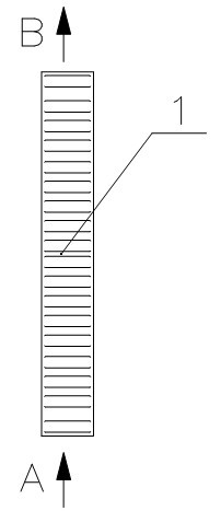
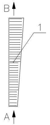
[0020] Such as figure 2 as shown, figure 2 It is a cross-sectional schematic diagram of Embodiment 1 of the present invention. Depend on figure 2 It can be seen that the fins of the direct air-cooled condenser of the present invention have a cross-sectional shape of a right-angled trapezoid. The cross section of the fin 1 is long and thin, the fin 1 is in a serpentine shape along the longitudinal direction, and the material of the fin 1 is aluminum or aluminum alloy. The cross-sectional shape of the fin 1 is a right-angled trapezoid, and its size increases from small to large along the air flow direction, and the width of the front end of the cross section facing the air flow is smaller than the width of the rear end.

[0021] In Embodiment 1, the length dimension of the cross section of the fin 1 is 180-285mm, the width dimension of the front end is 16-20mm, and the width dimension of the rear end is 19-26mm. .

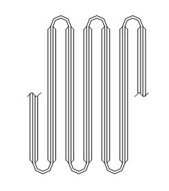
[0022] image 3 It is the serpentine curved shape of t...

Embodiment 2

[0025] Figure 4 It is a cross-sectional schematic diagram of embodiment 2 of the present invention. Depend on Figure 4 It can be seen that the present invention is a direct air-cooled condenser fin, the fin 1 has an isosceles trapezoidal cross-sectional shape, and the length of the fin 1 along the direction of the base pipe is a serpentine curved shape; the size of the fin 1 is similar to that of the first embodiment. The difference between Embodiment 2 and Embodiment 1 is mainly in the shape of the fins 1 .


PUM


Abstract

The invention relates to a direct air-cooling condenser fin which is applied to the exhaust-steam condensation field of turbines of thermal power plants, steam turbines in chemical and air separation industries and the like. The direct air-cooling condenser fin is characterized in that: the cross section of the fin (1) is shaped like a trapezoid and the size of the fin (1) is increased along with the flow direction of air. By means of the direct air-cooling condenser fin, the volume of hot air after air expansion is contained and the flow velocity of the air remains unchanged when the air flows through the fin, so that the resistance at the air side of the direct air-cooling condenser fin can be decreased to achieve the purpose of reducing the energy consumption of a fan and meet the requirements of the conservation-minded society. When the direct air-cooling condenser fin is applied to direct air-cooling condensers of large-scale thermal power plants, the advantage of low resistance is more prominent.

Description

technical field [0001] The invention relates to a fin of a direct air-cooled condenser. It is used in steam turbines in thermal power plants, steam turbines in chemical industry and air separation industry and other waste steam condensation fields. Background technique [0002] The steam turbine and exhaust steam discharged from the steam turbine need to be condensed into water and sent to the boiler for recycling. In order to save water resources, direct air-cooled condensers for exhaust steam condensation are widely used at home and abroad. The heat exchange elements used in direct air-cooled condensers are finned tubes that enhance heat exchange outside the tubes. Although there are many forms, the most widely used finned tubes are called single-row tubes. The single-row tube is composed of a base tube and fins. The cross-sectional shape of the base tube is a rectangular flat tube, and its two ends are arc-shaped; the cross-section of the fin is also rectangular, and th...

Claims


Application Information

Patent Timeline
Patent Type & Authority Applications(China)
IPC IPC(8): F28F1/12F28F21/08
Inventor 薛海君张健
Owner SHUANGLIANG ECO ENERGY SYST CO LTD
Learn More