Satellite locating pseudorange difference method

A pseudo-range differential and satellite positioning technology, which is applied to satellite radio beacon positioning systems, measuring devices, instruments, etc., can solve problems such as inconsistency of correction numbers, and achieve the effect of flexible operation mode, accurate pseudo-range positioning and convenient broadcasting.

Inactive Publication Date: 2012-07-25
CHINESE ACAD OF SURVEYING & MAPPING
View PDF4 Cites 12 Cited by
  • Summary
  • Abstract
  • Description
  • Claims
  • Application Information

AI Technical Summary

Problems solved by technology

In addition, if the entire reference station network performs error correction of double-difference pseudo-range observations according to the double-difference mode, the double-difference correction numbers of each subnetwork are independent of each other, so there are inconsistencies in the correction numbers of different subnetworks

Method used


Image

  • Satellite locating pseudorange difference method
  • Satellite locating pseudorange difference method
  • Satellite locating pseudorange difference method

Examples


Embodiment Construction

[0036] In order to make the purpose, technical solution and advantages of the present invention clearer, the present invention will be further described in detail below in conjunction with the accompanying drawings and specific embodiments.

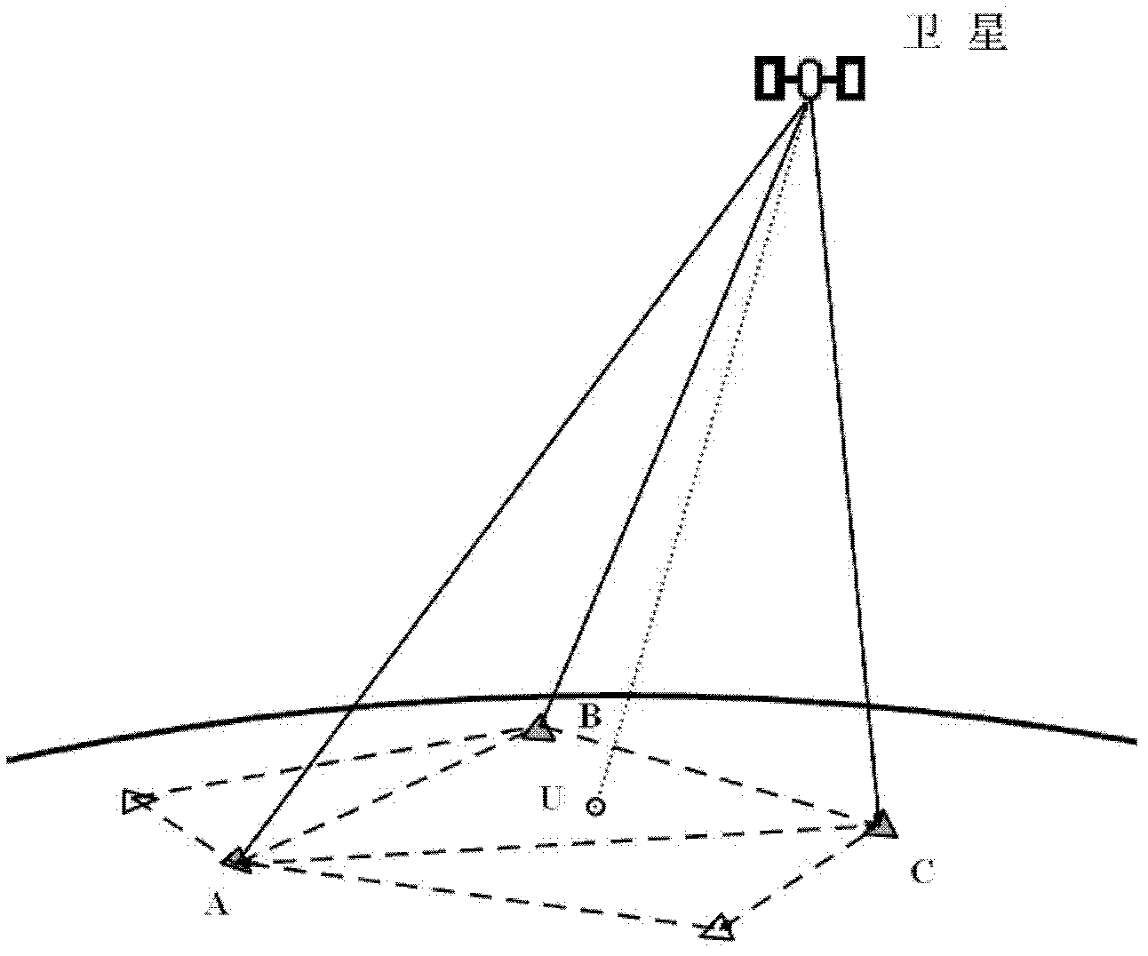
[0037] figure 1 Schematic diagram of undifferenced pseudorange error correction. Such as figure 1 As shown, the stations A, B, C, ... are the base station network, and the station U is the rover. The satellite transmits the signal through different propagation paths and propagates the observation signal to each station. In addition to the influence of the error of the satellite and receiver hardware in this process, it is mainly affected by the tropospheric, ionospheric delay and satellite orbit positioning errors on the propagation path. , and these main positioning errors are time-space dependent, so the observation data of the reference station network can be used to eliminate / weaken the relevant positioning errors at the user. Sinc...


PUM


Abstract

The invention provides a satellite locating pseudorange difference method. The method comprises the steps that: the observation data of a reference station network is utilized to acquire the error corrections of the non-pseudorange observed values of all the reference stations; the error corrections of the satellite non-pseudorange observed values of all the reference stations are processed, the error corrections of the non-pseudorange observed values of the satellites of all the roving stations are obtained through calculation, wherein the error corrections of the non-pseudorange observed values of the satellites of all the roving stations contain various error influences of the pseudorange observed values; and the error corrections of the non-pseudorange observed values of the satellites of all the roving stations are adopted to launch the pseudorange locating process of the roving stations.

Description

technical field [0001] The invention relates to the field of computer applications, in particular to a satellite positioning pseudo-range difference method. Background technique [0002] In satellite positioning, single-point positioning is performed using pseudo-range observations, and the real-time positioning accuracy is generally several meters. If the pseudo-range differential technology is used, decimeter-level real-time positioning technology can be obtained. However, the traditional single-station pseudo-range difference has a short working distance, and the positioning accuracy decreases rapidly with the increase of the distance. The working distance and positioning accuracy of the pseudo-range difference technology based on a network of multiple reference stations are superior to the traditional single-station pseudo-range difference. [0003] The current network pseudo-range difference method uses double-difference mode to eliminate errors such as satellite cloc...

Claims


Application Information

Patent Timeline
Patent Type & Authority Applications(China)
IPC IPC(8): G01S19/41
Inventor 祝会忠高星伟秘金钟程鹏飞徐彦田
Owner CHINESE ACAD OF SURVEYING & MAPPING
Why Eureka
Try Eureka