Electronic endoscope system
An electronic endoscope, blood vessel technology, applied in endoscopy, medical science, surgery, etc., can solve the problem of difficult blood vessel observation, and achieve the effect of improving visibility
- Summary
- Abstract
- Description
- Claims
- Application Information
AI Technical Summary
Problems solved by technology
Method used
Image
Examples
no. 1 Embodiment approach
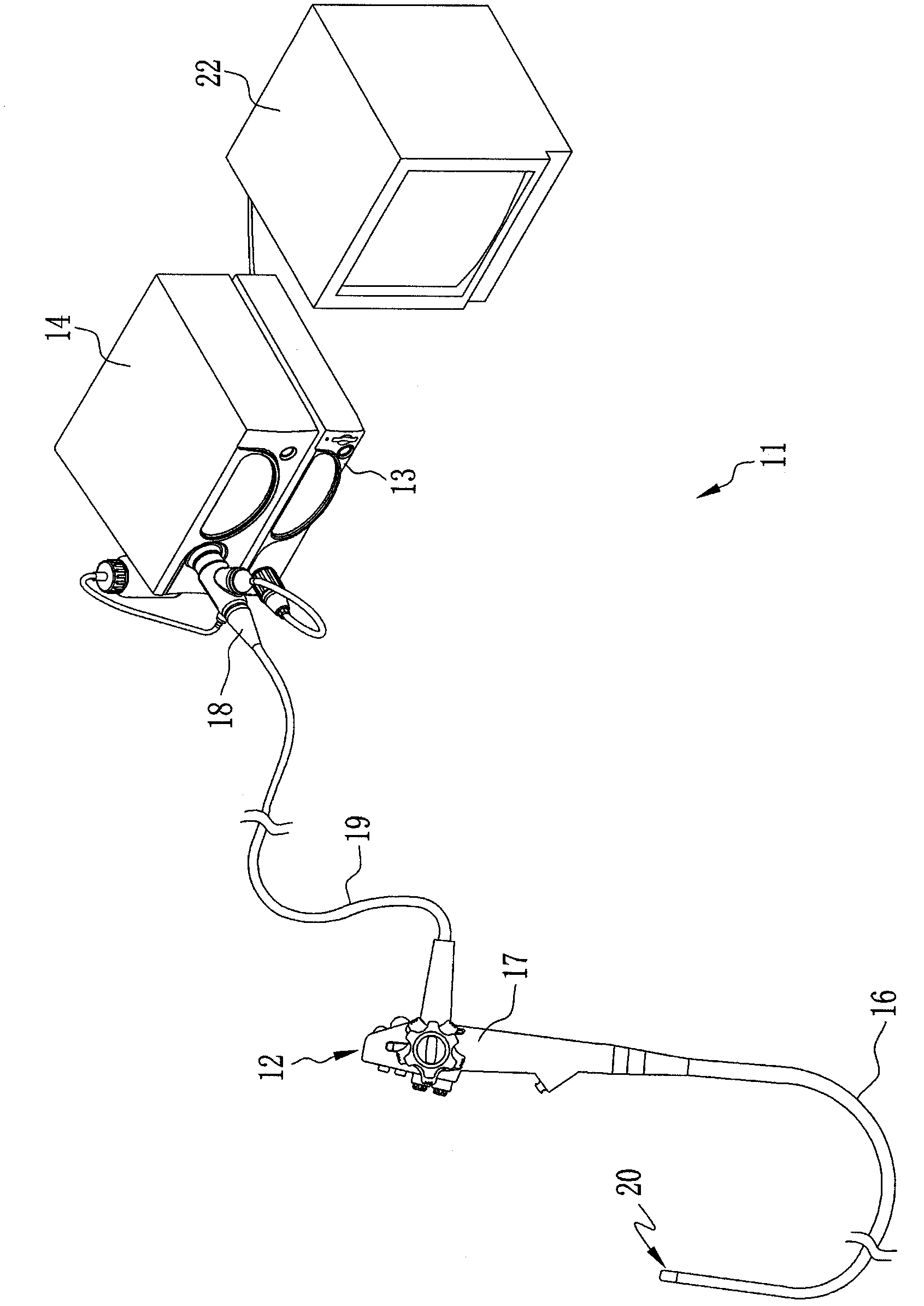
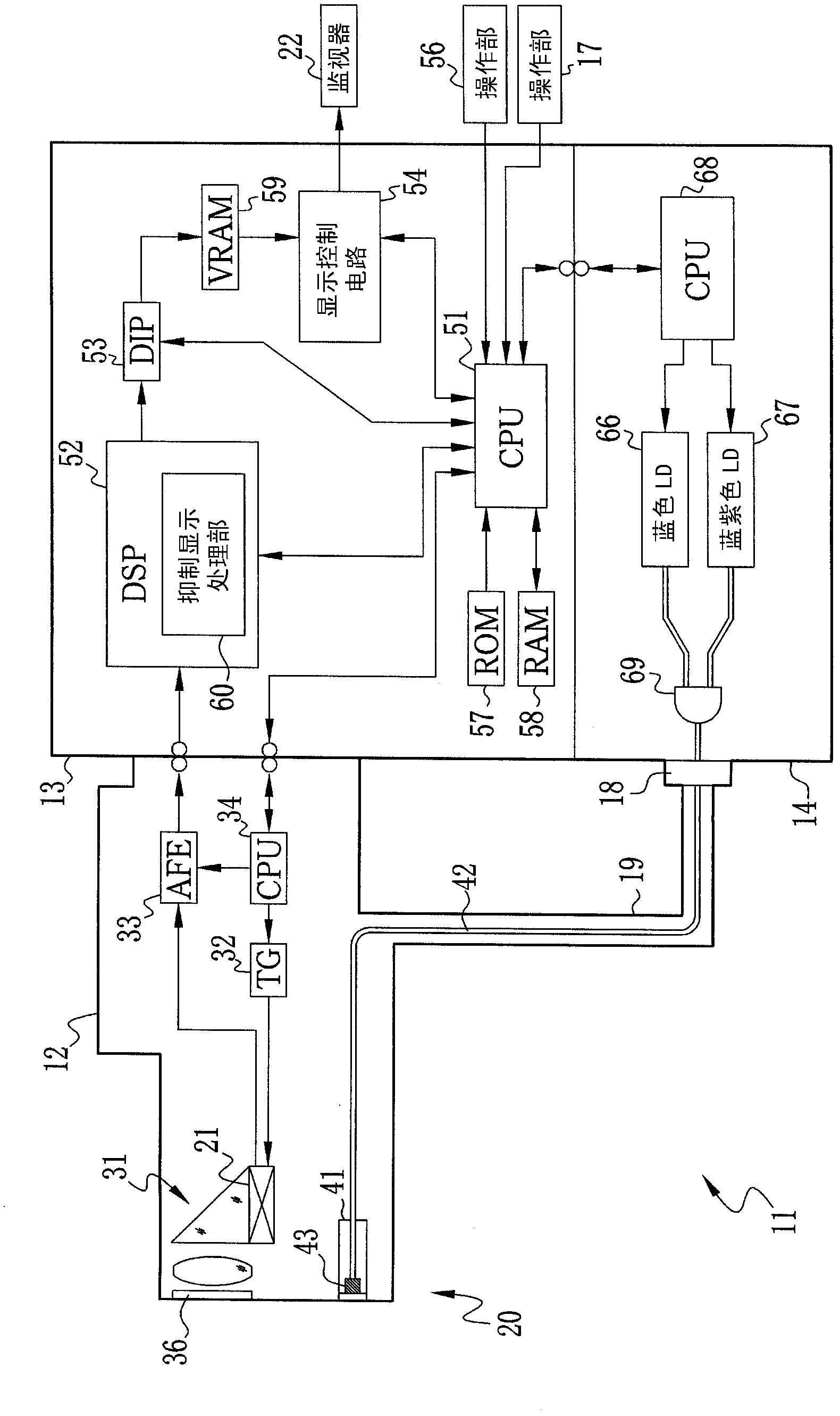
[0050] Such as figure 1 As shown, the electronic endoscope system 11 includes an electronic endoscope 12 , a processing device 13 , and a light source device 14 . The electronic endoscope 12 includes: a flexible insertion portion 16 inserted into the body of the subject; an operation portion 17 connected to the base end portion of the insertion portion 16; a connector 18 connected to the processing device 13 and the light source device 14; A universal flexible wire 19 is connected between the operation part 17 and the connector 18 . A CCD-type image sensor (refer to FIG. figure 2 , hereinafter referred to as CCD)21.
[0051] The following operating parts are provided in the operating part 17: an air supply / water supply button, which is used to spray air or water from the angled handle or the front end of the insertion part 16 that makes the front end part 20 bend up, down, left and right; A shutter button for recording; a zoom button for instructing enlargement / reduction o...
no. 2 Embodiment approach
[0099] In the above-mentioned first embodiment, an example in which the medium-deep blood vessel 73 is suppressed and displayed was described, but the objects to be suppressed and displayed are not limited to the middle-deep blood vessel 73 . For example, when it is desired to observe the middle-deep blood vessel 73 , it is preferable to suppress the display of the superficial blood vessel 72 . Hereinafter, an example of suppressing the display of the superficial blood vessel 72 will be described as the second embodiment. In addition, the same reference numerals are assigned to the same components as those of the electronic endoscope system 11 of the first embodiment described above, and description thereof will be omitted.
[0100] Such as Figure 11 As shown, the electronic endoscope system 76 is a system that suppresses the display of the superficial blood vessels 72 according to settings, and the CPU 68 of the light source device 14 is provided with a light quantity ratio...
no. 3 Embodiment approach
[0124] In addition, the method of suppressing the display of the middle and deep blood vessels 73 was described in the first embodiment, and the method of suppressing the display of the superficial blood vessels 72 was described in the second embodiment. Display suppression function. This is because: which one of the superficial blood vessel 72 and the middle-deep blood vessel 73 is to be observed is different according to the pathological condition, and the electronic memory is replaced according to which one of the superficial blood vessel 72 and the middle-deep blood vessel 73 is to be observed. The looking glass system is very complicated, and the burden on the inspected person is relatively large.
[0125] In the case where a single electronic endoscope is equipped with the display suppression function of the middle-deep blood vessel 73 and the superficial blood vessel 72, as Figure 21 As in the electronic endoscope system 86 shown, it is only necessary to provide the s...
PUM
 Abstract
Description
Claims
Application Information
 - R&D Engineer
- R&D Manager
- IP Professional
- Industry Leading Data Capabilities
- Powerful AI technology
- Patent DNA Extraction
Browse by: Latest US Patents, China's latest patents, Technical Efficacy Thesaurus, Application Domain, Technology Topic, Popular Technical Reports.
© 2024 PatSnap. All rights reserved.Legal|Privacy policy|Modern Slavery Act Transparency Statement|Sitemap|About US| Contact US: help@patsnap.com


