
Automatic millstone welder

A welding machine and grinding disc technology, applied in the mechanical field, can solve the problems affecting the welding quality, the performance of the grinding disc, the displacement of the cutter head, etc., and achieve the effect of good welding effect, high quality of the grinding disc, and uniform welding temperature

Active Publication Date: 2012-08-01
浙江振兴阿祥集团有限公司
View PDF4 Cites 40 Cited by
  • Summary
  • Abstract
  • Description
  • Claims
  • Application Information

AI Technical Summary

Problems solved by technology

However, the cutter heads need to be welded to the grinding disc one by one, and the welding will generate high temperature. Since the cutter heads are close together one by one, the adjacent welded cutter heads are easily displaced by the high temperature when welding one cutter head. Seriously affect the welding quality and the performance of the grinding disc

Method used


Image

  • Automatic millstone welder
  • Automatic millstone welder
  • Automatic millstone welder

Examples


Embodiment 1

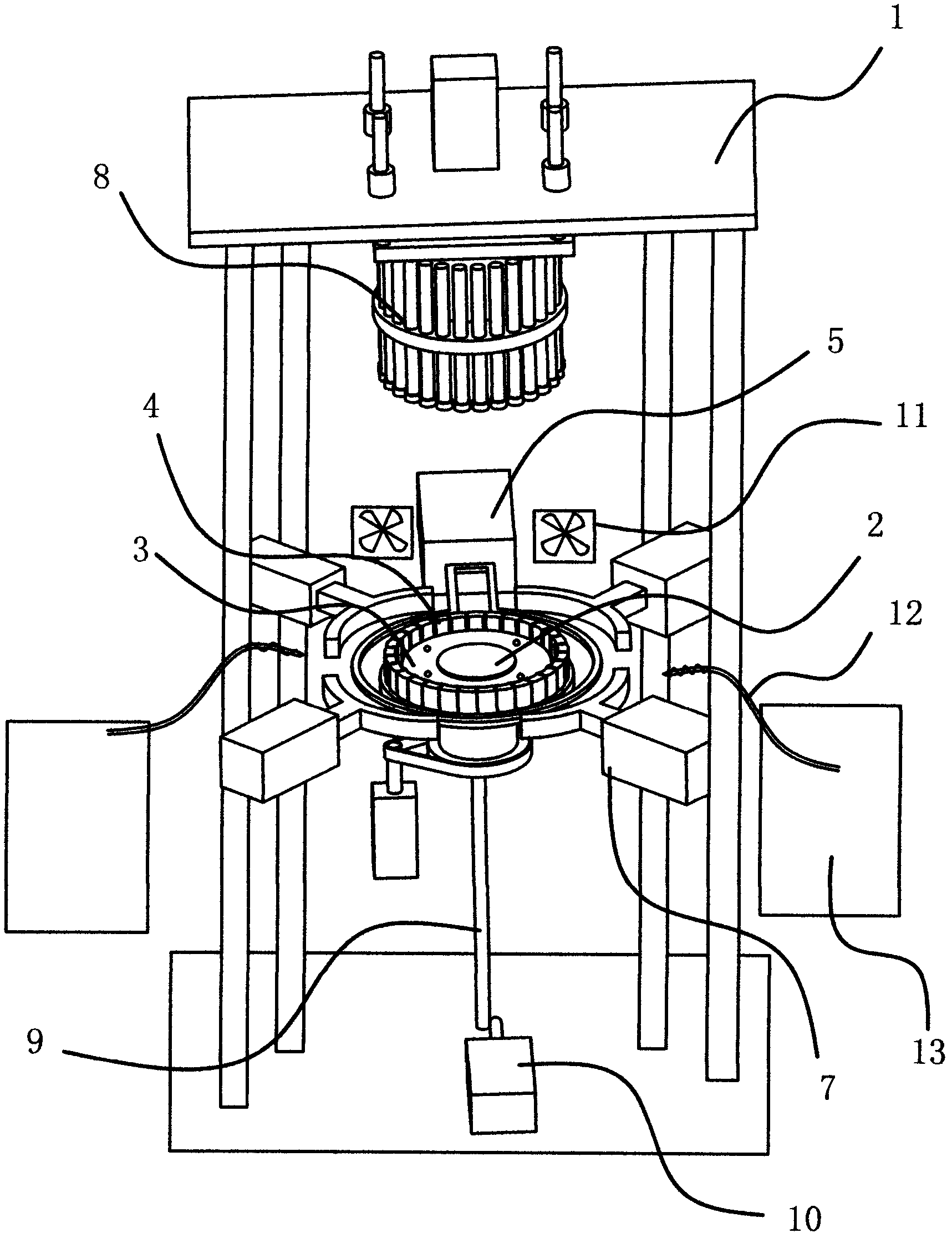
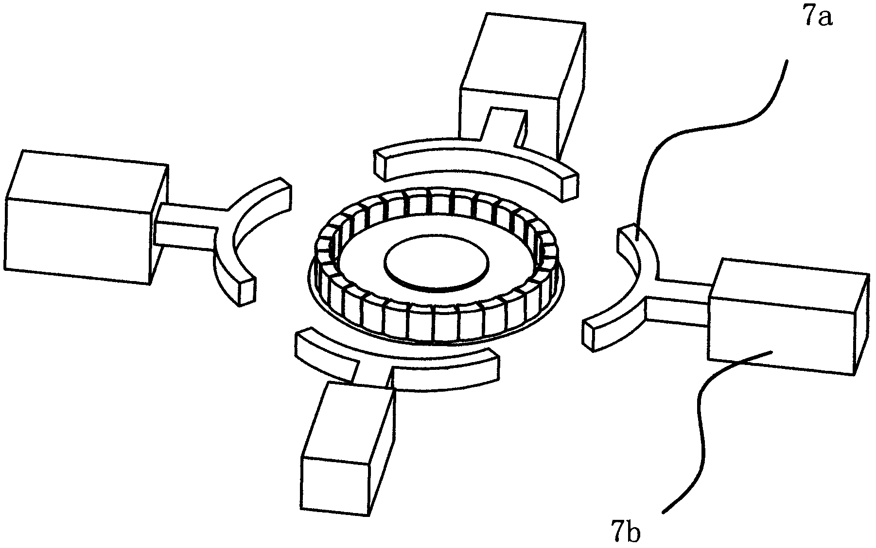
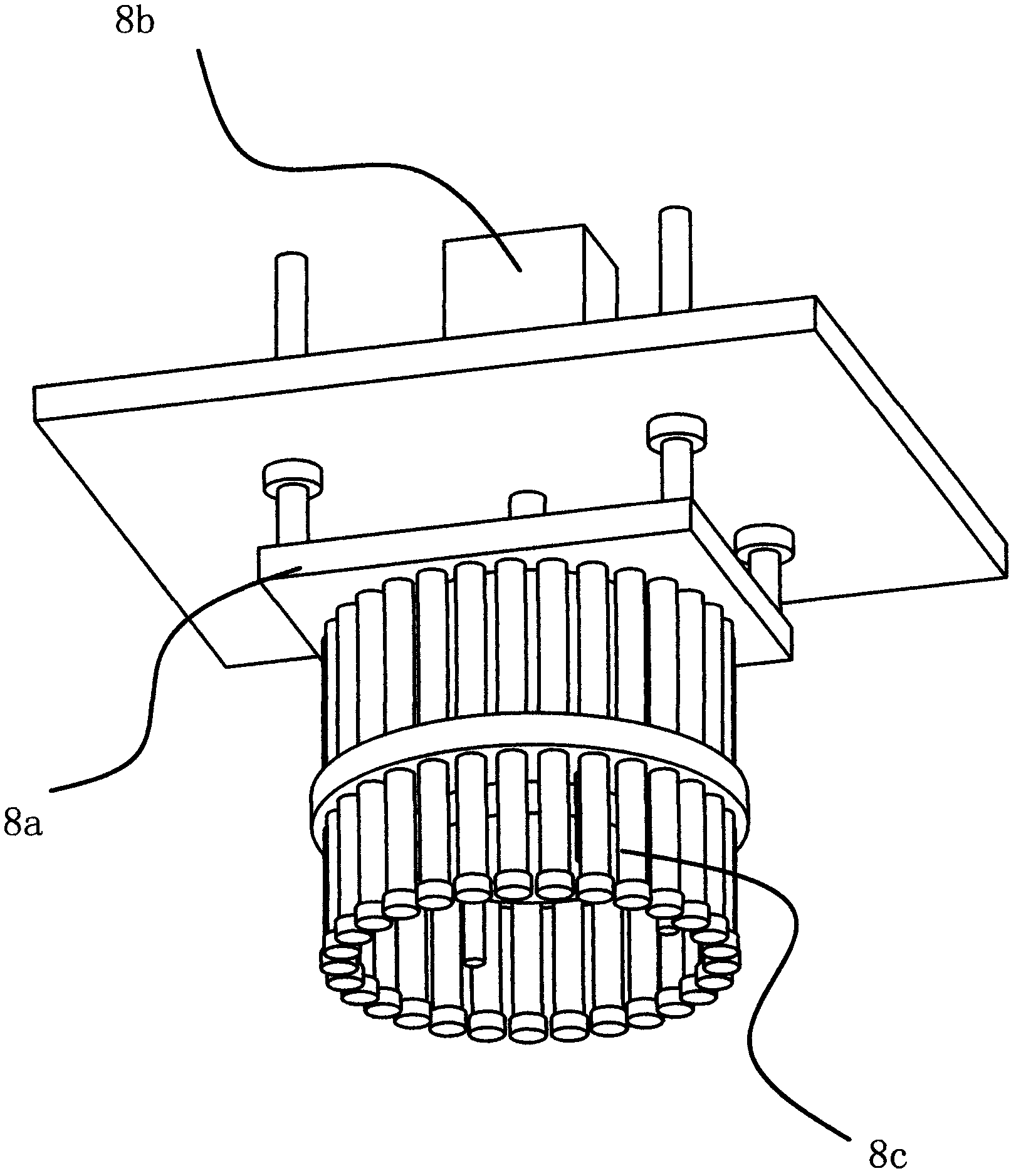
[0026] The edge of the grinding disc 3 has steps for positioning the cutter heads 4, and several cutter heads 4 are evenly distributed on the steps in the circumferential direction. like figure 1 As shown, the automatic grinding disc welding machine has a frame 1 and a working platform 2, the grinding disc 3 can be fixed on the working platform 2, and the outer ring of the working platform 2 is provided with a high-frequency induction for high-temperature heating and welding of the grinding disc 3 and the cutter head 4. Coil device 6. The working platform 2 is driven to rotate by the motor 5, and a correction device 7 is provided on the periphery of the working platform 2 to enable the cutter head 4 to be accurately positioned on the grinding disc 3, and a correcting device 7 that can squeeze the cutter head 4 and place it directly above the working platform 2 is provided. It is fixed on the pressing device 8 on the step of the grinding disc 3 .

[0027] Specifically, as fi...

Embodiment 2

[0029] The structure of embodiment two is basically similar to embodiment one, as Figure 5 As shown, the difference is that in embodiment one, the working platform 2 is a liftable structure, and in embodiment two, the high-frequency induction coil device 6 is a liftable structure, and a screw 9a is connected to the bottom of the high-frequency induction coil device 6, and the rotation of the screw rod 9a can drive The high-frequency induction coil device 6 moves up and down, and the screw rod 9a is driven by a stepping motor 10a. The purpose is all the same, all for the high-frequency induction coil device 6 and the correction device 7 not to interfere with each other in the work of the whole automatic grinding disc welding machine.

[0030] Although this article uses a lot of 1. frame; 2. working platform; 3. grinding disc; 4. cutter head; 5. motor; 6. high-frequency induction coil device; 7. correction device; One; 8, top pressure device; 8a, bracket; 8b, cylinder two; 8c,...


PUM


Abstract

The invention provides an automatic millstone welder, which belongs to the technical field of machinery. The welder solves the problems that welding quality is poor and welding efficiency is low in existing welding process of diamond millstones. The automatic millstone welder comprises a frame and a working platform. A millstone can be fixed on the working platform. A high-frequency induction coil device is disposed on the periphery of the working platform and the high-frequency induction coil device can perform high-temperature heating and welding to the millstone and bit tools. The working platform is driven to rotate by a motor. A correction device which enables the bit tools to be positioned to the millstone accurately is disposed on the periphery of the working platform. A pressing device which can press the bit tools and fix the bit tools on steps of the millstone is disposed right above the working platform. The automatic millstone welder is fine in welding effect, high in welding efficiency, and the welded millstone has high quality.

Description

technical field [0001] The invention belongs to the technical field of machinery and relates to an automatic disc welding machine. Background technique [0002] The automatic grinding disc welding machine is a machine that welds the diamond cutter head on the disc body through high-frequency heating. The grinding disc is composed of a disc body and a diamond cutter head. There are steps on the disc body, and the diamond cutter head is positioned on the step. The existing grinding disc welding machine welds and fixes the cutter heads one by one on the disc body through a butt welding machine or brazing. edge. [0003] For example, an edging wheel and its manufacturing process provided by the State Intellectual Property Office of the People's Republic of China [patent number: 200710028022.9, announcement number: CN101049684], including a diamond cutter head set on a metal grinding disc, and a metal connection is embedded at the bottom of the cutter head The cutter head is we...

Claims


Application Information

Patent Timeline
Patent Type & Authority Applications(China)
IPC IPC(8): B23K13/01
Inventor 项大清
Owner 浙江振兴阿祥集团有限公司
Learn More