Mounting bracket for overhead working

A technology for installing brackets and high-altitude operations, applied in lifting frames, lifting devices, etc., can solve problems such as difficulties, large volumes, and dangerous air ducts, and achieve the effects of low production costs, multiple application fields, and a wide range of applications

Inactive Publication Date: 2012-08-01
ZHEJIANG DINGLI MACHINERY CO LTD
View PDF4 Cites 5 Cited by
  • Summary
  • Abstract
  • Description
  • Claims
  • Application Information

AI Technical Summary

Problems solved by technology

However, it is very difficult to use during the installation process. First, the space is limited; second, the height is relatively high; third, it has a huge volume; fourth, it is heavy, etc.
At present, the straight-arm aerial work platform is used to lift it, but the existing aerial work platform can only realize the functions of lifting and transporting, and the air duct is easy to shake and fall off during the lifting and transporting process, which has many problems. It is a big safety hazard, and after lifting, it is necessary to manually place the air duct at the installation position or when it is tilted by itself, the air duct will move or even fall out of the installation position due to inaccurate position, causing danger
It can only lift the air duct to the installation position, and cannot perform precise installation by itself

Method used


Image

  • Mounting bracket for overhead working
  • Mounting bracket for overhead working
  • Mounting bracket for overhead working

Examples


Embodiment

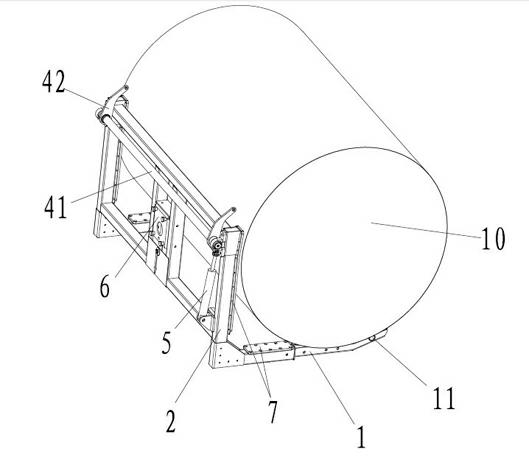
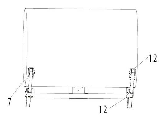
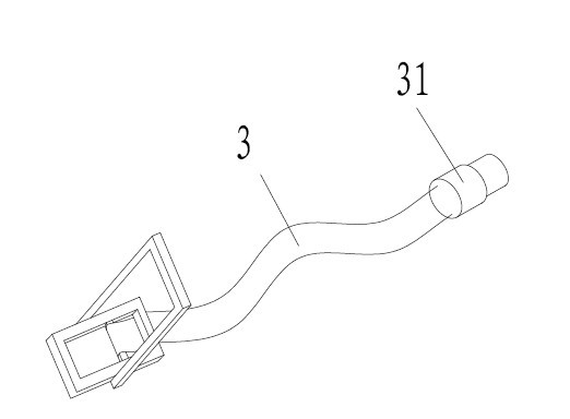
[0036] As shown in the accompanying drawings, a mounting bracket for aerial work includes a frame body. The frame body includes a horizontal support bracket 1 and a side support bracket 2 arranged perpendicularly to each other. The frame body is provided with a steering support device. It is used to connect the connecting seat 6 of the steering support device and the locking device for fixing the object to be installed; the locking device includes a tight rope 3 connected between the horizontal support bracket 1 and the side support bracket 2, and is arranged on One end of the tight rope 3 is connected to the tensioning assembly for tensioning the tight rope 3 on the support 2 . The tensioning assembly includes a rotating shaft 41 arranged on the upper part of the side support bracket 2, a crank arm 42 located at both ends of the rotation shaft 41 and rotating around the rotation shaft 41 as an axis, and a piston rod and a crank arm 42 arranged at the lower part of the side sup...


PUM


Abstract

The invention belongs to the field of overhead working, in particular to a mounting bracket for overhead working. The mounting bracket for overhead working comprises a bracket body, wherein the bracket body comprises a transverse supporting bracket and a side lying bracket which are vertically arranged mutually; a steering supporting device, a connecting seat used for connecting the steering supporting device and a locking device used for fixing an object to be mounted are arranged on the bracket body; the locking device comprises a tight rope connected between the transverse supporting bracket and the side lying bracket and a tensioning assembly which is arranged on the side lying bracket, connected with one end of the tight rope and used for tensioning the tight rope; and the tensioning assembly also comprises a rotation shaft arranged on the upper part of the side lying bracket, a crank arm which is arranged at both ends of the rotation shaft and rotated by taking the rotation shaft as a shaft core, a piston rod arranged on the lower part of the side lying bracket and a telescopic oil cylinder hinged with the lower end of the crank arm. The mounting bracket has the advantages of simplicity in structure, low cost, great flexibility, precise and sensitive control and good micromotion performance, and an overhead working machine can be applied to more environments and more fields.

Description

technical field [0001] The invention belongs to the field of aerial work, and in particular relates to a mounting bracket for aerial work. Background technique [0002] The current ventilation ducts are generally relatively large, and in large comprehensive factories, ventilation ducts are often used. However, it is very difficult to use during the installation process. First, the space is limited; second, the height is relatively high; third, it has a huge volume; fourth, it is heavy and so on. At present, the straight-arm aerial work platform is used to lift it, but the existing aerial work platform can only realize the functions of lifting and transporting, and the air duct is easy to shake and fall off during the lifting and transporting process, which has many problems. It is a big safety hazard, and after lifting, it is necessary to manually place the air duct at the installation position or when it is dumped by itself, the position of the air duct is not accurate, an...

Claims


Application Information

Patent Timeline
Patent Type & Authority Applications(China)
IPC IPC(8): B66F7/28B66F7/22
Inventor 许树根
Owner ZHEJIANG DINGLI MACHINERY CO LTD
Why Eureka
Try Eureka