Oil pan structure

A technology of oil pan and structure, applied in the direction of engine components, machine/engine, engine lubrication, etc., can solve the problems of engine speed increase, oil cut-off, etc., to speed up temperature rise, prevent burns, and shorten warm-up running time Effect

Inactive Publication Date: 2012-08-01
DAIKYONISHIKAWA CORP
View PDF7 Cites 5 Cited by
  • Summary
  • Abstract
  • Description
  • Claims
  • Application Information

AI Technical Summary

Problems solved by technology

[0009] However, under the oil pan structure described in the Japanese Utility Model Laid-Open Publication No. Sho 63-014007, if the oil discharge amount of the oil pump increases with the increase of the engine speed, the following disadvantages will occur
[0010] For example, shortly after the engine is started, the engine speed increases sharply, and when the oil injection volume of the oil pump increases, the engine oil stored in the first oil storage chamber alone cannot meet the requirements of the increased oil injection volume, and a breakdown may occur. oil phenomenon

Method used


Image

  • Oil pan structure
  • Oil pan structure
  • Oil pan structure

Examples


Embodiment approach 1

[0115] Like the first embodiment, the electric actuator 107 of the second embodiment is also configured to receive a control signal from the control unit C to generate a rotational force, and the rotational force is applied to the worm 106 b via the shaft 73 .

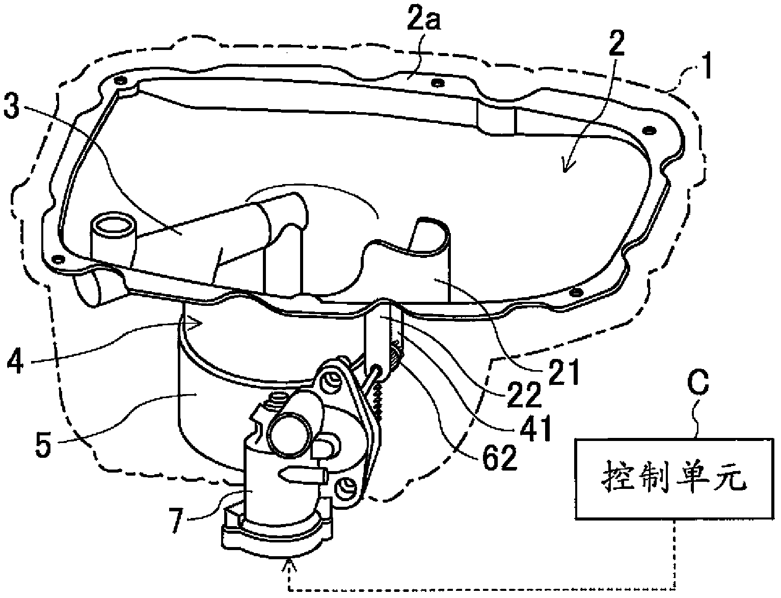
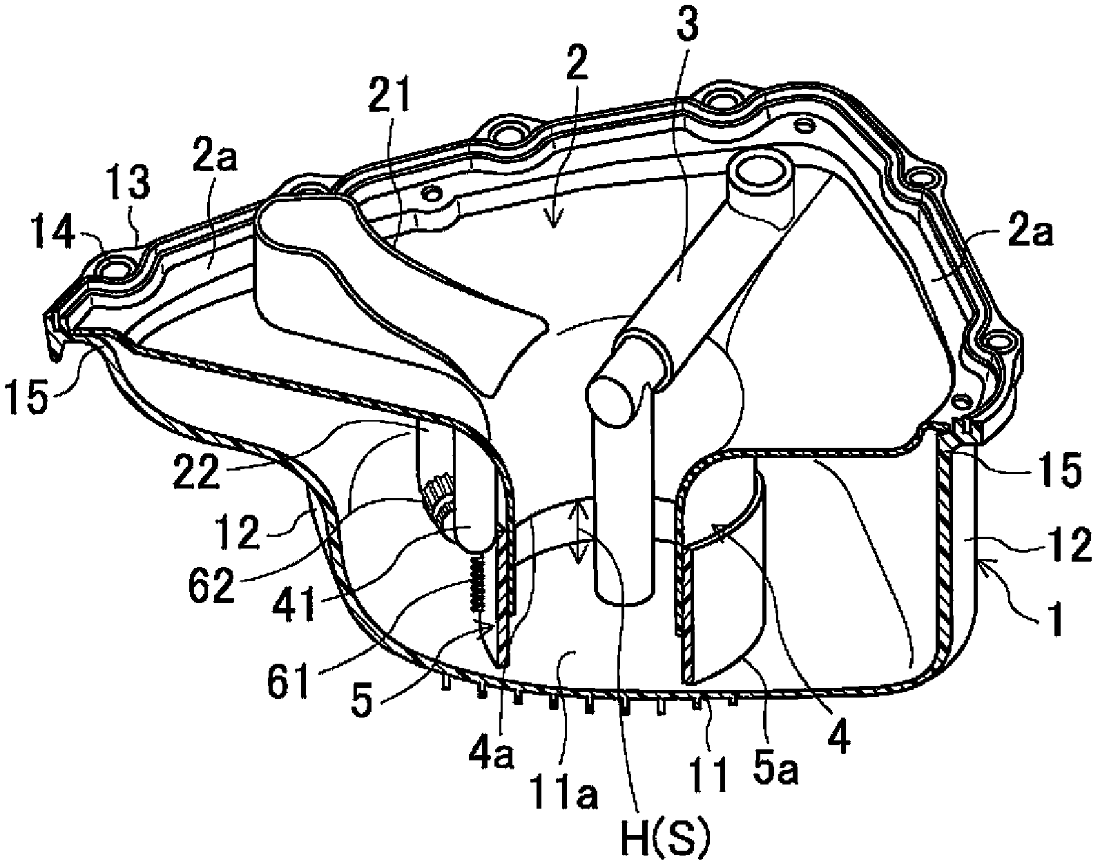
[0116] The opening area adjusting mechanism M adjusts the opening area S of the communication port 9 between the oil passage body 4 and the bottom surface 11a of the oil pan 1 by using the above-mentioned structure. Specifically, the opening area S is increased or decreased by rotating and moving the partition wall body 105 in the circumferential direction.

[0117] In addition, although the specific control flow is not described, it actually controls using the same control flow as that of 1st Embodiment.

[0118] Therefore, substantially the same effect as that of the first embodiment can be obtained in this second embodiment as well. In particular, in the second embodiment, the opening area S is adjusted by rotating...


PUM


Abstract

Disclosed is an oil pan structure for an engine. The internal space of the oil pan structure is divided into a first engine oil storage chamber and a second engine oil storage chamber by a cylindrical engine oil channel body. A circulating port is arranged between the engine oil channel body and the oil pan to make the engine oil circulate between the first engine oil storage chamber and the second engine oil storage chamber. The opening size of the circulating port can be adjusted according to the operating state of the engine. A minimum opening size is ensured for incomplete obstruction of the circulation of the engine oil in the circulating port. Therefore, the time for the operation of the heating of turbine can be shortened when the engine is in the refrigerating state, with reduced oil consumption, and the temperature of the engine oil can rise rapidly. The fuel cut-off phenomenon during the time when the engine speed rises sharply can be avoided.

Description

technical field [0001] The present invention relates to an oil pan structure mounted on a lower portion of an engine, and more particularly to an oil pan structure in which the shape of an engine oil storage portion changes according to the operating state of the engine. Background technique [0002] Generally, engine oil is circulated inside the engine to lubricate or cool the sliding parts of the engine. An oil pan for storing this engine oil is installed at the lower part of the engine. [0003] In order to prevent the engine oil from being scattered or deflected to one side, or to receive the dripped engine oil (hereinafter referred to as oil return) after lubricating the various sliding parts of the engine and guide the oil to a specified place on the oil pan, the An oil baffle is arranged on the oil pan. [0004] The disclosed content in Japanese Utility Model Publication No. 62-2257 is as follows: the oil baffle is used to allow the return oil to return to a positio...

Claims


Application Information

Patent Timeline
Patent Type & Authority Applications(China)
IPC IPC(8): F01M11/00
Inventor 榎田智志
Owner DAIKYONISHIKAWA CORP
Why Eureka
Try Eureka