Supercharge Your Innovation With Domain-Expert AI Agents!

Tapping back-off locking nut

A technology of anti-loosening nuts and undercuts, which is applied in the direction of nuts, screws, bolts, etc., can solve the problems of reduced work efficiency, complicated process, and increased process, and achieves the effect of convenient operation, simple process, and anti-rotation

Inactive Publication Date: 2012-08-01
SUZHOU INDAL PARK XINKAI PRECISION FASTENERSCO
View PDF5 Cites 3 Cited by
  • Summary
  • Abstract
  • Description
  • Claims
  • Application Information

AI Technical Summary

Problems solved by technology

[0002] At present, the existing nuts fixed on the plate are usually riveted. After the riveting, the nut will rotate on the plate, which is not conducive to the installation of bolts on the nut, and some nuts are screwed on the plate by threaded connection. , when vibration occurs, the nut is easy to loosen. When installing, the thread must be tapped first, and the thread on the outside of the nut is used in conjunction with the threaded hole on the plate, which increases the process and reduces work efficiency; there is also an insert nut One way is to install it on the plastic sheet, one is to inject it directly into the sheet. After this method is embedded, the size of the thread of the insert cannot be changed, which reduces the flexibility of assembly; the other is to heat the product and embed it into the plastic part. In this method, the process is more complicated and inconvenient for the operator to operate; sometimes the shape, position and quantity of the inserts are different, and it is difficult to realize automation in the injection molding process; the shrinkage rate of the metal insert is much smaller than that of the surrounding plastic Material, after the installation is completed, the plastic parts are prone to warping, and the excessive internal stress can cause local cracks; metal inserts are generally customized, and their production costs increase accordingly

Method used


Image

  • Tapping back-off locking nut
  • Tapping back-off locking nut
  • Tapping back-off locking nut

Examples


Embodiment Construction

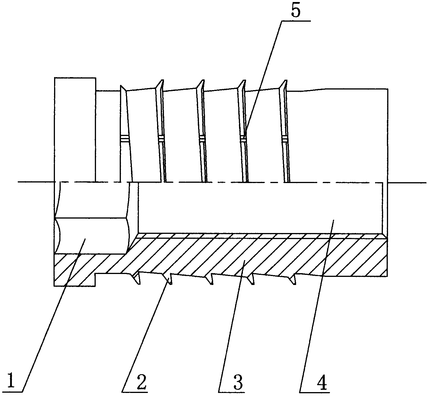
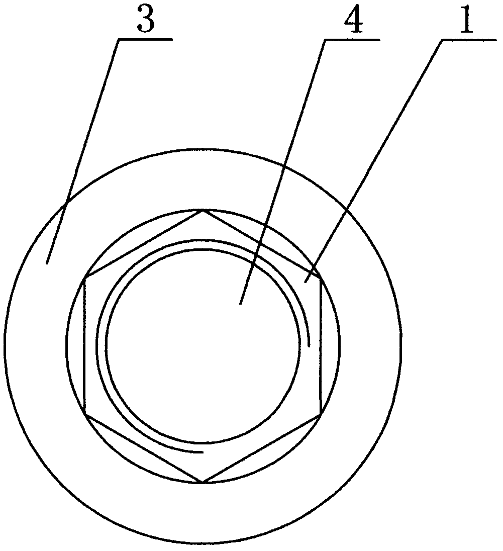
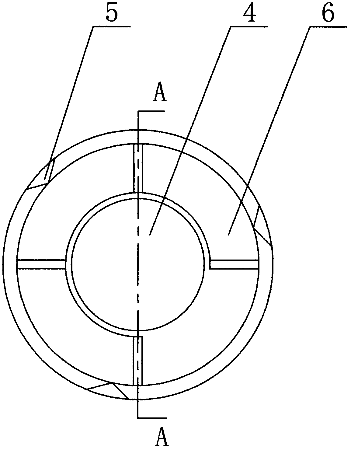
[0013] like Figure 1 to Figure 4 A self-tapping undercut anti-loosening nut is shown, comprising a nut column body 3, the interior of the nut column body 3 is provided with a threaded hole 4 and an inner hexagonal drive head 1 at one end of the threaded hole 4, and the nut column body 3 is provided with There are self-tapping undercuts 2 with a taper; the self-tapping undercuts 2 are provided with three inclined grooves 5; Raised 6.

[0014] This kind of nut is installed when it needs to be used. It is usually installed on a plastic plate. The inner hexagonal drive head 1 is driven by an electric tool, the nut rotates, and the self-tapping undercut tooth 2 is screwed into the mounting hole on the plastic plate by self-tapping. The debris produced by self-tapping is embedded in the chute 5 on the self-tapping undercut tooth 2, which can achieve the effect of anti-loosening and anti-rotation. Prevents rotation of the nut; the diameter of the mounting hole is slightly smaller ...


PUM


Abstract

The invention relates to a tapping back-off locking nut which comprises a nut stud body, wherein a thread hole and an inner hexagon driving head at one end of the thread hole are arranged inside the nut stud body; tapping back-off teeth with taper are arranged on the nut stud body; at least one chute is formed in the tapping back-off teeth; and at least one wedged protrusion is arranged at the other end of the nut stud body, which is away from the inner hexagon driving head. Due to the adoption of the tapping back-off teeth, the convolution and the loosening of the nut can be prevented; materials generated by tapping enter the chute in the tapping back-off teeth, so that the convolution of the nut can be prevented; in addition, the nut is combined with a mounting hole more closely; the wedged protrusion can enter the mounting hole more conveniently and is better attached to the bottom of the mounting hole, and thus the sliding and loosening are prevented; nuts with threads in different specifications can be conveniently arranged according to the requirement; the convenience in operation and simpleness in process are realized; and a heating and embedding method is avoided, so that the phenomena that a plastic member is warped caused by heating and the crack occurs due to over great internal stress are reduced.

Description

technical field [0001] The invention relates to a nut, in particular to a self-tapping undercut anti-loosening nut. Background technique [0002] At present, the existing nuts fixed on the plate are usually riveted. After the riveting, the nut will rotate on the plate, which is not conducive to the installation of bolts on the nut, and some nuts are screwed on the plate by threaded connection. , when vibration occurs, the nut is easy to loosen. When installing, the thread must be tapped first, and the thread on the outside of the nut is used in conjunction with the threaded hole on the plate, which increases the process and reduces work efficiency; there is also an insert nut One way is to install it on the plastic sheet, one is to inject it directly into the sheet. After this method is embedded, the size of the thread of the insert cannot be changed, which reduces the flexibility of assembly; the other is to heat the product and embed it into the plastic part. In this meth...

Claims


Application Information

Patent Timeline
IPC IPC(8): F16B39/282F16B25/10
Inventor 田小娟
Owner SUZHOU INDAL PARK XINKAI PRECISION FASTENERSCO
Features
  • R&D
  • Intellectual Property
  • Life Sciences
  • Materials
  • Tech Scout
  • Unparalleled Data Quality
  • Higher Quality Content
  • 60% Fewer Hallucinations
Learn More