Stable-type damping device

A shock-absorbing device and a stable technology, applied in the direction of spring/shock absorber, spring, magnetic spring, etc., can solve the problem of large variation of shock absorber shock-absorbing force, small repulsive force impact force, and failure to meet safety requirements And other issues

Active Publication Date: 2012-08-01
JIANGSU DEPENG AIR CONDITION CO LTD
View PDF3 Cites 14 Cited by
  • Summary
  • Abstract
  • Description
  • Claims
  • Application Information

AI Technical Summary

Problems solved by technology

This kind of shock absorber can meet the requirements of energy saving and environmental protection, but it cannot meet the safety requirements, because the closer the distance between the two magnets, the greater the repulsive force between them; The distance between the two magnets is relatively large, and the repulsive force is too small relative to the impact...

Method used


Image

  • Stable-type damping device
  • Stable-type damping device
  • Stable-type damping device

Examples


Embodiment 1

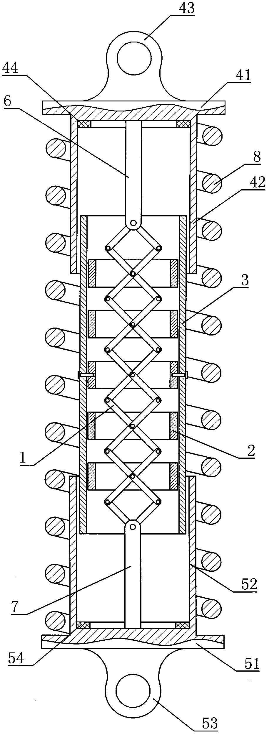
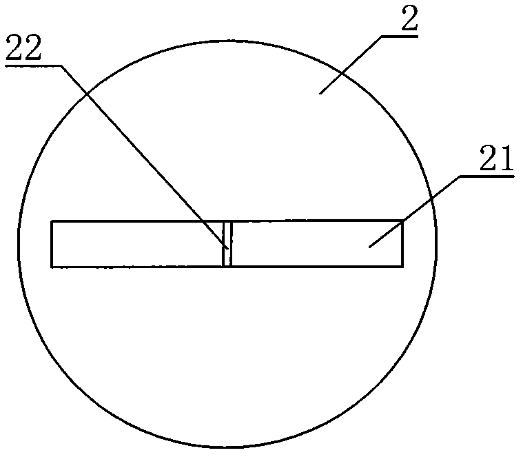
[0018] Such as figure 1 As shown, the stable shock absorber includes five opposite magnets 2 with opposite magnetic poles, and the magnets 2 are hinged on the cross scissor type telescopic frame 1, as figure 2 As shown, the magnet 2 is provided with a telescopic frame movable channel 21, and the telescopic frame movable channel 21 is provided with a telescopic frame hinge shaft 22 fixedly connected with the magnet 2, and the cross scissor type telescopic frame 1 is connected with the The telescopic frame hinge shaft 22 is hinged. The outer side of the magnet 2 is set with a limit guide inner sleeve 3, the magnet 2 in the middle is fixedly connected with the limit guide inner sleeve 3, and the rest of the magnets 2 are left between the limit guide inner sleeve 3. There is a gap of 0.1mm to 0.8mm, so that when the magnet 2 moves in the limit guide inner sleeve 3, it will not interfere with the inner wall of the limit guide inner sleeve 3, which can improve the limit guide inne...

Embodiment 2

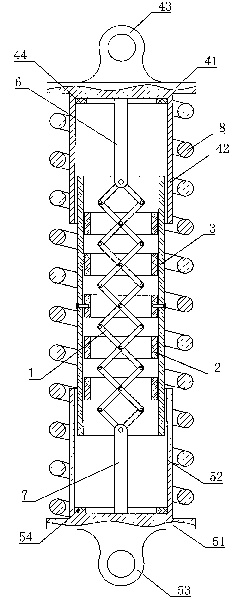
[0024] This embodiment is basically the same as Embodiment 1, except that in this embodiment, between the upper end cover 41 and the lower end cover 51 , along the upper guide outer sleeve 42 and the lower guide outer sleeve, Shock absorbing springs 8 are evenly distributed on the outer circumference of sleeve 52, and two, three or more shock absorbing springs 8 can be installed. There is a balanced tension between the lower end caps 51 , so that the upper end cap 41 and the lower end cap 51 maintain a substantially parallel position.


PUM


Abstract

The invention discloses a stable-type damping device, which comprises at least two magnets. Opposite magnetic poles of the magnets are adjacent, the magnets are hinged on a cross shear-type expansion bracket, retaining-and-guiding inner sleeves are sleeved outside the magnets, upper end seats and lower end seats are disposed at both ends of the retaining-and-guiding inner sleeves respectively andconnected with both ends of the cross shear-type expansion frame respectively, and damping springs are installed between the upper end seats and the lower end seats. Since opposite magnetic poles of adjacent magnets are arranged oppositely, the closer the distance, the greater the attraction; when severe vibration occurs, the damping springs are compressed and deformed greatly, the elasticity of the damping springs increases linearly with the deformation; when the deformation of the damping springs increases, the distance between adjacent magnets decreases, the attraction increases geometrically, a part of increased elasticity is offset, in other words, impact force to car frames is decreased. By the stable-type damping device, stable damping can be realized when the elasticity of damperscan be kept changing mildly and nonlinearly within a bigger deformation range.

Description

technical field [0001] The invention relates to a shock absorber, in particular to a shock absorber which utilizes magnetic force to achieve stable shock absorption. Background technique [0002] With the rapid development of the automobile industry in recent years, users require not only safety and practicality, but also environmental protection and energy saving. The automobile shock absorber is an important part of the automobile. It is mainly used to suppress the shock when the spring rebounds after absorbing the shock and the impact from the road. Traditional automobiles use oil-air shock absorbers. When the frame (or body) and the car When the bridges are vibrated and there is relative movement, the piston in the shock absorber is driven to move up and down, so as to achieve the purpose of shock absorption. Due to the aging of the seals, this kind of shock absorber is easy to cause oil leakage and environmental pollution, which violates the concepts of energy saving, ...

Claims


Application Information

Patent Timeline
IPC IPC(8): F16F15/02F16F15/04F16F6/00
Inventor 周德田刁久新王京梅陈小迎
Owner JIANGSU DEPENG AIR CONDITION CO LTD
Why Eureka
Try Eureka