Method based on uniform-speed moving point target for measuring transverse magnification of optical system

A technology of lateral magnification and optical system, which is applied in the field of lateral magnification measurement of optical systems based on uniform moving point targets, can solve the problems of low repeatability of lateral magnification measurement, achieve small errors, reduce errors, and improve repeatability Effect

Active Publication Date: 2014-12-03
HARBIN INST OF TECH
View PDF9 Cites 0 Cited by
  • Summary
  • Abstract
  • Description
  • Claims
  • Application Information

AI Technical Summary

Problems solved by technology

[0028] The present invention aims at the large distortion optical system of the above-mentioned existing measurement method, which is not suitable for measurement in a large field of view, but in a small field of view, there is the problem of low repeatability of lateral magnification measurement, and the existing measurement device has the problem of separation In view of the problem of focusing, a method and device for measuring the lateral magnification of an optical system is proposed. This method can improve the repeatability of measurement results in a small field of view and is more suitable for measuring the lateral magnification of a large distortion optical system; the device can eliminate defocus Influence on the measurement results, further improving the repeatability of the measurement results

Method used


Image

  • Method based on uniform-speed moving point target for measuring transverse magnification of optical system
  • Method based on uniform-speed moving point target for measuring transverse magnification of optical system
  • Method based on uniform-speed moving point target for measuring transverse magnification of optical system

Examples


Embodiment Construction

[0048] Specific embodiments of the present invention will be further described in detail below in conjunction with the accompanying drawings.

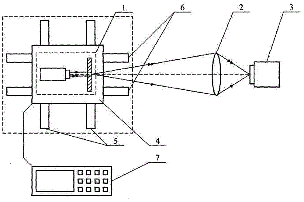
[0049] figure 1 It is a structural schematic diagram of an optical system lateral magnification measurement device based on a uniform moving point target; the device includes a point target 1, an optical system 2, an image sensor 3, a slider 4, a first guide rail 5 perpendicular to the optical axis direction, and a controller 7, The point target 1 is imaged onto the surface of the image sensor 3 through the optical system 2; and, the device also includes a second guide rail 6 along the optical axis direction, and the slider 4 carrying the point target 1 is installed on the first guide rail 5 and the second guide rail 5. On the guide rail 6, when the controller 7 controls the slider 4 to move at a constant speed on the first guide rail 5, the controller 7 controls the slider 4 to move on the second guide rail 6, and the movement in the ...


PUM


Abstract

A method and a device based on a uniform-speed moving point target for measuring transverse magnification of an optical system belongs to the field of measuring equipment characterized by optical methods. The method has the following steps: imaging for a point target is performed to obtain a linear image when the point target is in uniform motion; and the transverse magnification of the optical system of an image sensor can be calculated based on the fact that the theoretical cutoff frequency equals to the frequency corresponding to the first minimum of the modulation transfer function value obtained within the frequency domain through the practical measurement. A sliding block for bearing the point target in the device is installed on a first guiding rail and a second guiding rail; a controller is used for controlling the sliding block to move on the second guiding rail when the controller is used for controlling the sliding block to perform uniform motion on the first guiding rail, the movement in the two directions are matched, so that the point target can be always focused and imaged on the surface of the image sensor during the movement; and through adopting the method and the device for measuring the transverse magnification of the optical system, the error reduction of single measurement can be facilitated, so that the repeatability of measurement results can be improved.

Description

technical field [0001] The method for measuring the lateral magnification of an optical system based on a uniform moving point target belongs to the field of metrology equipment characterized by the use of optical methods, and in particular relates to a point light source that moves in a straight line at a uniform speed as a target, and uses the constant moving image MTF in the frequency domain to measure the optical system. Method for lateral magnification of the system. Background technique [0002] The lateral magnification of the optical system is a very important parameter in the field of medicine and precision measurement. It not only indicates the technical index of the optical system, but also can use this technical index to carry out precise measurement of other parameters. However, how to obtain the lateral magnification of an optical system is the primary problem in carrying out this work. [0003] 1. The measurement method of the lateral magnification of the opt...

Claims


Application Information

Patent Timeline
Patent Type & Authority Patents(China)
IPC IPC(8): G01M11/02
Inventor 谭久彬赵烟桥刘俭
Owner HARBIN INST OF TECH
Why Eureka
Try Eureka