3D time-of-flight camera and method

A time-of-flight and camera technology, applied in the field of 3D time-of-flight, can solve problems such as uneven response radiation and compensation for sensor inhomogeneity

Inactive Publication Date: 2012-08-01
SONY CORP
View PDF2 Cites 36 Cited by
  • Summary
  • Abstract
  • Description
  • Claims
  • Application Information

AI Technical Summary

Problems solved by technology

The reason for this is the need to compensate for sensor inhomogeneities, since quantum wells A and B and their amplification paths do not respond equally to radiation

Method used


Image

  • 3D time-of-flight camera and method
  • 3D time-of-flight camera and method
  • 3D time-of-flight camera and method

Examples


Embodiment Construction

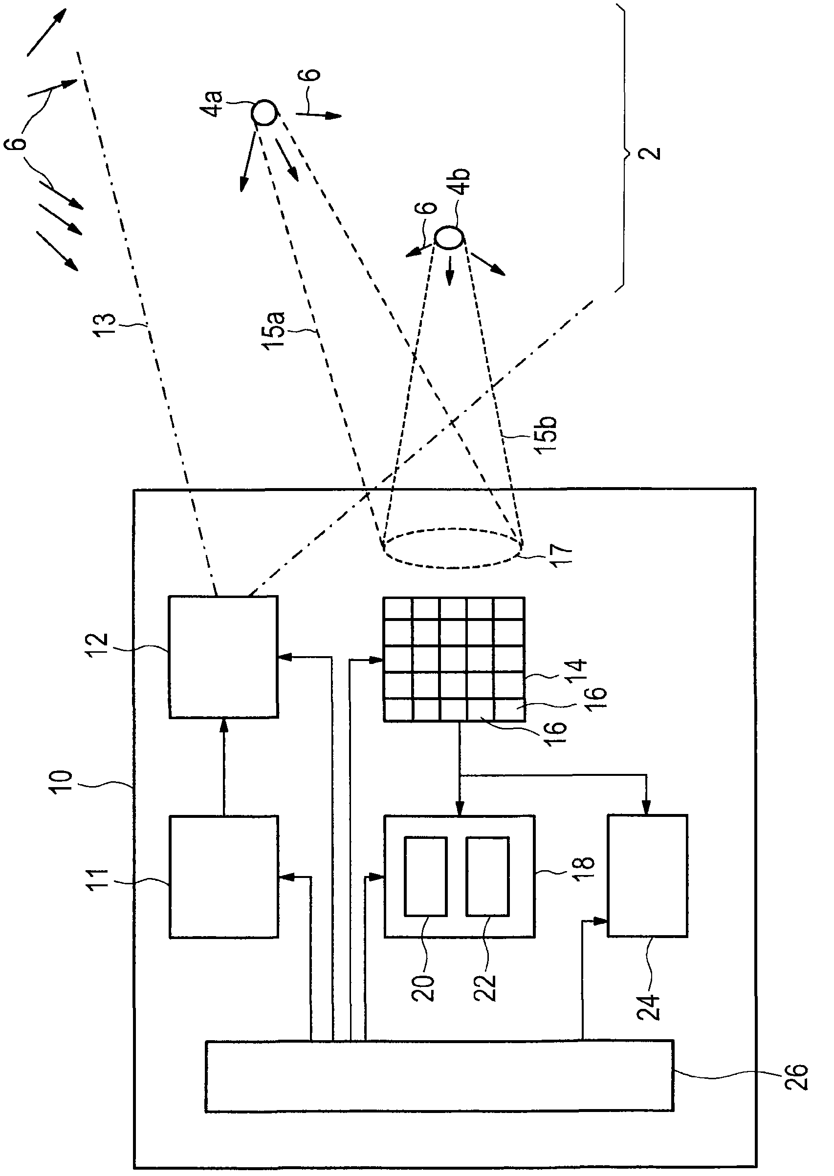
[0034] exist figure 1 A schematic diagram of the general layout of a 3D ToF camera 10 according to the present invention is shown in . Such cameras 10 are generally used to obtain information about the scene 2 . Such information may specifically include information used to generate a depth image of the scene, information about a phase shift of the scene, or environmental information about the scene. As an example, the following description will focus on the acquisition of the depth image, in particular, on the acquisition of the distance information about the figure 1 The distance of one or more objects of scene 2 (background object 4 a and foreground object 4 b ) from camera 10 in the embodiment shown in . In addition to the reflectivity of one or more objects 4 of the scene 2 and the intensity of unmodulated radiation (which includes ambient light and unmodulated light emitted by radiation sources) 6, this distance information is to be determined to be able to generate t...


PUM


Abstract

The present invention relates to a 3D time-of-flight camera and a corresponding method for acquiring information about a scene, in particular for acquiring depth images of a scene, information about phase shifts between a reference signal and incident radiation of a scene or environmental information about the scene. To increase the frame rate, the proposed camera comprises a radiation source (12) that generates and emits electromagnetic radiation (13) for illuminating said scene (2), a radiation detector (14) that detects electromagnetic radiation (15a, 15b) reflected from said scene (2), said radiation detector (14) comprising one or more pixels (16), in particular an array of pixels, wherein said one or more pixels individually detect electromagnetic radiation reflected from said scene, wherein a pixel comprises two or more detection units (161-1, 161-2, ...) each detecting samples of a sample set of two or more samples and an evaluation unit (18) that evaluates said sample sets of said two or more detection units and generates scene-related information from said sample sets, wherein said evaluation unit comprises a rectification unit (20) that rectifies a subset of samples of said sample sets by use of a predetermined rectification operator defining a correlation between samples detected by two different detection units of a particular pixel, and an information value calculator (22) that determines an information value of said scene-related information from said subset of rectified samples and the remaining samples of the sample sets.

Description

technical field [0001] The present invention relates to 3D time-of-flight (TOF) for acquiring information about a scene, in particular for acquiring a depth image of the scene, information about the phase shift between a reference signal and incident radiation of the scene, or environmental information about the scene. 3D time-of-flight) cameras and corresponding 3D time-of-flight methods. Furthermore, the invention relates to a processor and corresponding processing method for use in such a 3D time-of-flight camera and method. Also, the present invention relates to a computer program for realizing such a processing method on a computer and a computer-readable non-transitory medium storing such a computer program. Background technique [0002] A 3D time-of-flight (ToF) camera obtains a depth image by determining the time it takes for radiation (preferably light) to travel from a source to an object and back to the camera. This is usually achieved by intermittently illumina...

Claims


Application Information

Patent Timeline
Patent Type & Authority Applications(China)
IPC IPC(8): G06T7/00G01S17/894
CPCG01S17/89G01S17/894
Inventor 米克·施密特克劳斯·齐默尔曼
Owner SONY CORP
Why Eureka
Try Eureka