
Eureka
For R&D, Eureka makes reading and utilizing patents & technical documents easy.
Eureka AIR
Designed for self-driven R&D workflows. Generate viable solutions, solve complex R&D challenges, empower your innovation with AI.

Eureka Materials
Designed for material experts only. Revolutionize your material R&D, from search, analyze, to developing new materials.

TechResearch
Generate reliable direction feasibility study reports for your R&D in just a few steps.

TechSeek
Discover and master advanced knowledge NOW. Basics, ideas, possibilities, all at once.

TechMind
As an expert in R&D Theories, TechMind can generates customized viable solutions instantly.

TechRisk
Analyze your overall solution with one click, know your potential R&D risks in advance.

TechMonitor
Get weekly tech updates, stay abreast of the latest tech innovations and key insights.
General clamp piece for three-phase three-pole amorphous iron cores
A three-phase three-column, amorphous technology, used in electrical components, inductance/transformer/magnet manufacturing, circuits, etc., can solve the problems of backlog of components, high production cost, and many components, and achieve convenient operation and simple structure. , the effect of reducing production costs
- Summary
- Abstract
- Description
- Claims
- Application Information
AI Technical Summary
Problems solved by technology
Method used
Image

Examples
Embodiment 1
[0031] Example 1 (see attached Figure 4 and 5 ).
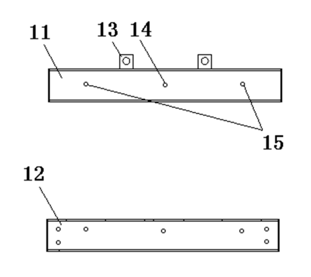
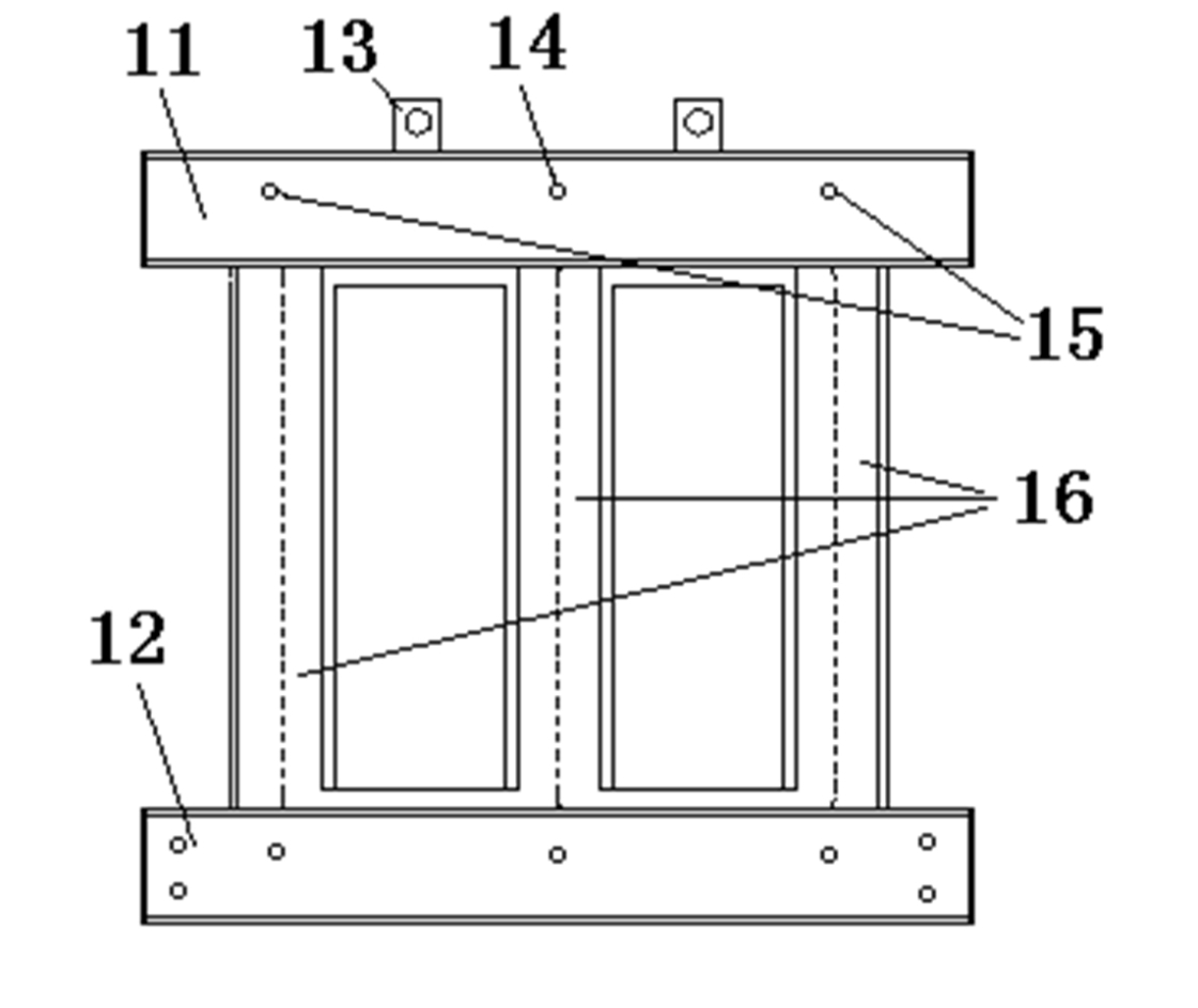
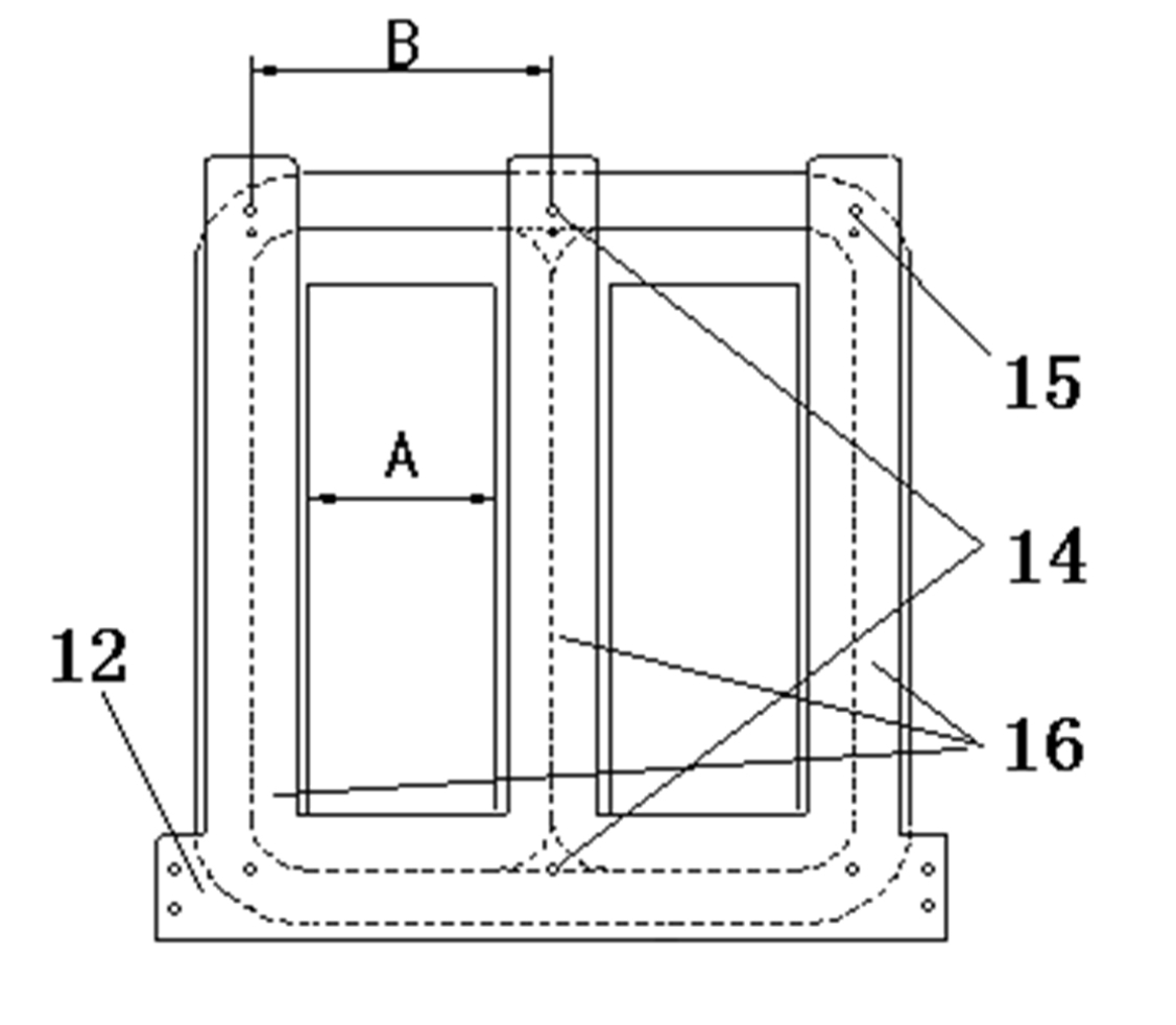
[0032] A three-phase three-column amorphous iron core universal clamp is composed of a horizontal strip-shaped upper clamp 21 and a lower clamp 22 . The upper clamping part 21 and the lower clamping part 22 are metal plates of grooved or non-troughed structure, and two lifting lugs are provided on the upper clamping part 21; A middle fixing pin hole 24 is set in the middle of the upper clamping piece 21 and a lower clamping piece 22 (both sides of the middle fixing pin hole 24 ) and side fixing pin slots 25 are set. Standard bolts can be used to clamp iron cores 36 of different sizes through the middle fixing pin hole 24 and the side fixing pin slots 25 . A clip can meet the requirements for manufacturing three-phase three-column amorphous iron cores of different sizes.
[0033] Why doesn't the present invention adopt a through groove structure on the upper clamping part 21 and the lower clamping part 22, isn't the vers...
Embodiment 2
[0035] Example 2 (see attached Figure 6 and 7 ).
[0036] A three-phase three-column amorphous iron core universal clamp is composed of a horizontal strip-shaped upper clamp 31 and a lower clamp 32 . The upper clamping part 31 and the lower clamping part 32 are metal plates of grooved or non-troughed structure, and two lifting lugs are provided on the upper clamping part 31; The middle fixing pin hole 34 is set in the middle of the upper clamping piece 31 and the lower clamping piece 32 (both sides of the middle fixing pin hole 34) and there are 3 to 5 pin holes (if necessary, you can Increase some pin holes, generally 3~5 pin holes are just passable) the side fixed pin hole 35 that constitutes. The bolts of the standard parts can be used to clamp the iron cores 36 of different types through holes at different positions in the middle fixing pin hole 34 and the side fixing pin holes 35 . A clamp can meet the requirements for manufacturing various types of three-phase thr...
PUM
 Abstract
Description
Claims
Application Information
 - R&D Engineer
- R&D Manager
- IP Professional
- Industry Leading Data Capabilities
- Powerful AI technology
- Patent DNA Extraction
Browse by: Latest US Patents, China's latest patents, Technical Efficacy Thesaurus, Application Domain, Technology Topic, Popular Technical Reports.
© 2024 PatSnap. All rights reserved.Legal|Privacy policy|Modern Slavery Act Transparency Statement|Sitemap|About US| Contact US: help@patsnap.com