Luminescent module

A technology of light-emitting modules and light-emitting parts, which is applied in the direction of electrical components, circuits, semiconductor devices, etc., and can solve problems such as the inability to change the color temperature

Inactive Publication Date: 2012-08-01
WINTEK CHINA TECH LTD +1
View PDF10 Cites 0 Cited by
  • Summary
  • Abstract
  • Description
  • Claims
  • Application Information

AI Technical Summary

Problems solved by technology

However, this kind of light-emitting diode cannot change the color temperature because the phosphor powder has been fixed.

Method used


Image

  • Luminescent module
  • Luminescent module
  • Luminescent module

Examples


Embodiment Construction

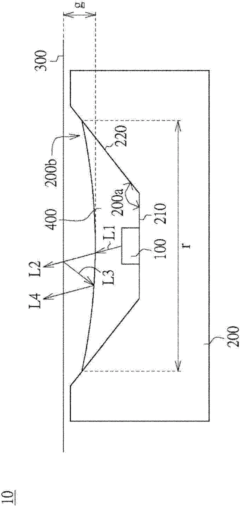
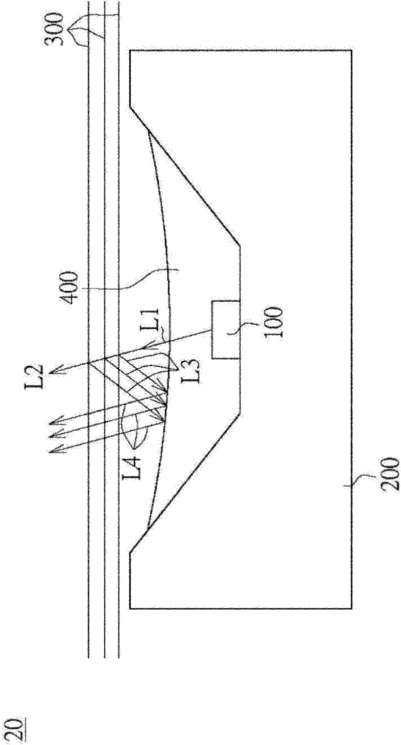
[0024] Please refer to figure 1 , which is a schematic diagram of a light emitting module according to a preferred embodiment of the present invention. The light emitting module 10 includes a light emitting element 100 , a substrate 200 , a thin film 300 and a phosphor layer 400 . The light emitting element 100 is, for example, a light emitting diode (LED) for emitting a light L1. The substrate 200 is, for example, a LED packaging substrate. The light emitting element 100 is disposed on the substrate 200 . The film 300 can be, for example, a diffusion film or a semi-transmissive and semi-reflective film. Part of the light L1 can pass through the film 300 to be the light L2 , and part of the light L1 can be reflected or scattered by the film 300 to be the light L3 . The phosphor layer 400 is disposed between the light emitting element 100 and the film 300 . The phosphor layer 400 is used to change the wavelength of the light L3 reflected by the film 300 . The light-emitti...


PUM


Abstract

The invention discloses a luminescent module which comprises a thin film, a luminescent part and a phosphor powder layer. The luminescent part is for emitting a beam, and the thin film is for permeating the partial beam and reflecting the partial beam. The phosphor powder layer is arranged between the luminescent part and the thin film, wherein the phosphor powder layer is for changing the partial beam reflected by the thin film.

Description

technical field [0001] The invention relates to a light-emitting module, and in particular to a light-emitting module with a fluorescent powder layer. Background technique [0002] A light emitting diode (Light Emitting Diode, LED) is a semiconductor element. At the beginning, it was mostly used as indicator lights, display panels, etc.; with the emergence of white light-emitting diodes, it was also used as lighting. It is a new type of light source in the 21st century, with advantages that traditional light sources cannot compare with, such as high efficiency, long life, and not easy to break. In the past, most of the white light emitting diodes were blue light emitting diode dies, and yellow phosphor was coated on top of them, so that the light emitted to the outside was white light. However, the color temperature of such light-emitting diodes cannot be changed because the phosphor powder has been fixed. Therefore, developing a light-emitting module capable of changing ...

Claims


Application Information

Patent Timeline
Patent Type & Authority Applications(China)
IPC IPC(8): H01L33/48H01L33/58H01L33/60
Inventor 陈冰彦叶志庭
Owner WINTEK CHINA TECH LTD
Why Eureka
Try Eureka