
Rotary traveling wave oscillator with high power output of multiple energy injection locking

An injection locking and oscillator technology, applied in pulse shaping and other directions, can solve the problems of low signal power, high substrate conductivity, high frequency signal loss, etc., and achieve the effect of increasing the range

Inactive Publication Date: 2012-08-01
FUDAN UNIV
View PDF7 Cites 5 Cited by
  • Summary
  • Abstract
  • Description
  • Claims
  • Application Information

AI Technical Summary

Problems solved by technology

There are mainly the following problems, first: the substrate conductivity of the silicon material process is large, resulting in relatively large loss of high-frequency signals and relatively low signal power
Second: With the reduction of the geometric size of the device, although the intrinsic gain is improved, the withstand voltage value of the device becomes very small, so it is difficult to achieve high power output

Method used


Image

  • Rotary traveling wave oscillator with high power output of multiple energy injection locking
  • Rotary traveling wave oscillator with high power output of multiple energy injection locking
  • Rotary traveling wave oscillator with high power output of multiple energy injection locking

Examples


Embodiment Construction

[0036] The present invention will be further described below in conjunction with the accompanying drawings.

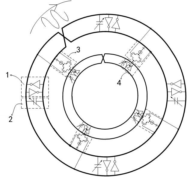
[0037] figure 1 The frame diagram of the system is shown. The rotating traveling wave oscillator based on high-order harmonic injection locking mainly includes three main parts. The first part is the oscillator that generates the fundamental frequency signal. This oscillator uses a distributed rotating traveling wave. The oscillator, the second part is a harmonic generating network circuit, the fundamental frequency signal generated by the rotating traveling wave oscillator generates higher harmonics through the harmonic generating network circuit. The third part is the injection-locked rotating traveling wave oscillator, and the harmonic generation network injects the generated high-order harmonic energy into this rotating traveling wave oscillator, thereby generating higher frequency oscillations.

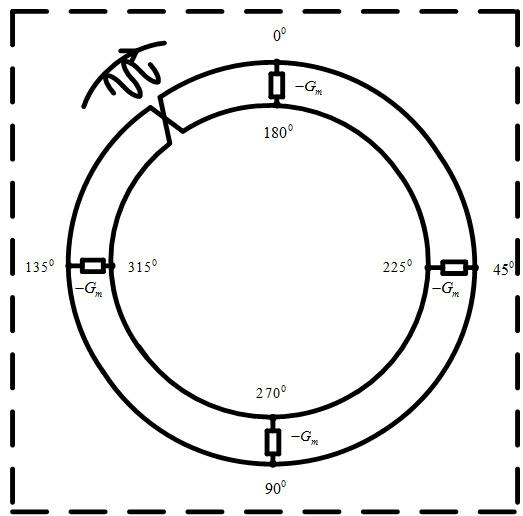
[0038] Specific circuits such as figure 2As shown, the two transm...


PUM


Abstract

The invention belongs to the technical field of millimeter wave integrated circuits, and particularly relates to a rotary traveling wave oscillator of multiple energy injection locking. The circuit mainly comprises a rotary traveling wave oscillator, a negative resistance network, a voltage controlled variable capacitor, a voltage controlled phase shifter and a harmonic generation circuit. Parasitic resistances in a capacitance device and an inductance device are high with the rising of the signal frequency, particularly when the frequency in ranges of millimeter waves or sub-millimeter waves in the integrated circuit, and simple capacitance inductance oscillator is difficult to achieve the output of wide tuning ranges and large power. According to the rotary traveling wave oscillator, a voltage-controlled rotary traveling wave oscillator is used to produce fundamental frequency signals to couple the harmonic generation circuit at different positions of the oscillator. The produced high sub-harmonic signals are injected into another oscillator to achieve oscillation with high frequency. The injection locking range is increased by injecting a plurality of energy and choosing appropriate phase of the injected signal.

Description

technical field [0001] The invention belongs to the technical field of radio frequency microwave integrated circuits, and in particular relates to a multi-energy injection-locked rotating traveling wave oscillator. Background technique [0002] With the advancement of integrated circuit process technology, the feature size of transistors is constantly shrinking in accordance with Moore's Law. The shrinking of transistors makes the frequency of the intrinsic gain of the transistors continue to increase, so that circuits based on silicon materials have also been greatly developed in the microwave field. Previous microwave integrated circuits were all made of gallium arsenide material, but the price of this material is relatively expensive, so microwave integrated circuits have not been widely used in the civilian field. Silicon materials have great advantages in price and integration, so if silicon materials can be used to realize microwave circuits with good performance, it ...

Claims


Application Information

Patent Timeline
Patent Type & Authority Applications(China)
IPC IPC(8): H03K5/08
CPCH03B5/1852
Inventor 任俊彦马顺利李宁许俊
Owner FUDAN UNIV
Learn More