Channel status indicator measuring method and system

A channel state indication and measurement method technology, applied in wireless communication, error prevention/detection through diversity reception, electrical components, etc., can solve the problem that SCell cannot be accurately scheduled, and achieve improved wireless resource utilization and significant scheduling gain Effect

Inactive Publication Date: 2012-08-01
ZTE CORP
View PDF0 Cites 87 Cited by
  • Summary
  • Abstract
  • Description
  • Claims
  • Application Information

AI Technical Summary

Problems solved by technology

[0007] In view of this, the main purpose of the present invention is to provide a channel state indication measurement method and system to solve the problem that the SCell cannot be accurately reported in the prior art because the UE cannot report the channel state indication in time and accurately after the SCell is successfully activated. scheduling problem

Method used


Image

  • Channel status indicator measuring method and system
  • Channel status indicator measuring method and system
  • Channel status indicator measuring method and system

Examples


Embodiment 1

[0094] In this embodiment, the UE is configured with PCell, SCell_1, and SCell_2, wherein SCell_1 is in the activated state and SCell_2 is in the deactivated state, and the CQI measurement of SCell_2 is performed, as shown in Figure 7 As shown, the specific implementation process includes the following steps:

[0095] Step 201: Before preparing to activate SCell_2, the eNB sends a MAC CE carrying a CQI measurement start indication to the UE in subframe n-4;

[0096] Here, the eNB may also send the MAC CE carrying the CQI measurement start indication to the UE in a subframe earlier than subframe n-4.

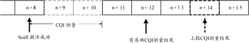
[0097] Here, the eNB may indicate in the MAC CE that the subframe for reporting the CQI of SCell_2 is n+8, then in step 204, the UE may determine that it needs to start at subframe n+2 according to the subframe position n+8 where the CQI measurement result is reported. CQI measurement of SCell_2.

[0098] Here, the eNB may also indicate to the UE by carrying the CQI measuremen...

Embodiment 2

[0112] In this embodiment, the UE is configured with PCell, SCell_1, and SCell_2, wherein both SCell_1 and SCell_2 are in the active state, and the process of performing CQI measurement is as follows Figure 8 As shown, the specific implementation process includes the following steps:

[0113] Step 301: The eNB pre-configures on the UE through RRC signaling that SCell_1 stops CQI measurement after deactivation, and SCell_2 continues CQI measurement after deactivation.

[0114]Step 302: eNB configures periodic CQI measurement reports for SCell_1 and SCell_2 through RRC signaling in advance.

[0115] Step 303: The eNB sends a MAC CE for deactivating SCell_1 and SCell_2 in subframe n to deactivate SCell_1 and SCell_2.

[0116] Step 304: The UE receives the MAC CE for deactivating SCell_1 and SCell_2 in subframe n, successfully decodes in subframe n+3, succeeds in demultiplexing in subframe n+6, and deactivates SCell_1 and SCell_2 in subframe n+8 success.

[0117] Step 305: UE ...

Embodiment 3

[0125] The UE is configured with PCell, SCell_1, and SCell_2, where both SCell_1 and SCell_2 are in the active state, and the process of performing CQI measurement is as follows: Figure 9 As shown, the specific implementation process includes the following steps:

[0126] Step 401: eNB configures periodic CQI measurement reports for SCell_1 and SCell_2 in advance through RRC signaling.

[0127] Step 402: The eNB sends a MAC CE for deactivating SCell_1 and SCell_2 in subframe n to deactivate SCell_1 and SCell_2.

[0128] Step 403: The eNB sends a MAC CE in subframe n for instructing to stop reporting the CQI measurement result of SCell_1 and continue reporting the CQI measurement result of SCell_2.

[0129] Step 404: UE receives MAC CE for deactivating SCell_1 and SCell_2 in subframe n, and deactivates SCell_1 and SCell_2 in subframe n+8 successfully.

[0130] Step 405: The UE receives the MAC CE indicating to stop the reporting of the CQI measurement result of SCell_1 and c...


PUM


Abstract

The invention discloses a channel status indicator (CSI) measuring method which comprises the steps of: an eNB sends a CSI measuring indication to a UE before an SCell is activated; and the UE carries out a CSI measurement according to the CSI measuring indication. Correspondingly, the invention further provides a CSI measuring system which can ensure that the UE reports an accurate CSI measurement result to the eNB after the SCell is successfully activated so that the SCell can be accurately scheduled after being successfully activated, which is conducive to the improvement of utilization rate of wireless resources and cell throughput, and a more significant scheduling gain especially for a situation of a larger number of activated Scells or more frequent activation or deactivation operations.

Description

technical field [0001] The invention relates to channel indication technology in the communication field, in particular to a channel state indication measurement method and system. Background technique [0002] The Evolved Universal Terrestrial Radio Access Network (E-UTRAN, Evolved Universal Terrestrial Radio Access Network) in the Long Term Evolution (LTE, Long Term Evolution) system of the Third Generation Partnership Project (3GPP, Third Generation Partnership Projects) consists of a base station (eNB) composition. The downlink multiple access technology of the LTE system is Orthogonal Frequency Division Multiple Access (OFDMA, Orthogonal Frequency Division Multiple Access), and the uplink multiple access technology is Single Carrier Frequency Division Multiple Access (SC-FDMA, Single Carrier Frequency Division Multiple Access) . The wireless interface protocol between eNB and user equipment (UE, UserEquipment) consists of physical layer (PHY, Physical layer), media ac...

Claims


Application Information

Patent Timeline
Patent Type & Authority Applications(China)
IPC IPC(8): H04L1/06H04W24/10
Inventor 张健
Owner ZTE CORP
Why Eureka
Try Eureka