Signaling optimization method and system for MTC devices set together

An optimization method and equipment technology, applied in the field of communication, can solve problems such as mobility management signaling peak value, waste of air interface resources, terminal power loss, etc., and achieve the effect of saving mobility management signaling

Active Publication Date: 2012-08-01
ZTE CORP
View PDF6 Cites 15 Cited by
  • Summary
  • Abstract
  • Description
  • Claims
  • Application Information

AI Technical Summary

Problems solved by technology

When a large number of these MTC devices move in the same direction at the same time and perform signaling interaction with the network to execute the mobility management process, it will cause a peak value of mobility management signaling and bring a large load to the network
And for such MTC devices that are co-located (for example, temporarily built or permanently built together and move in the same direction), from the perspective of terminal-to-network mobility, their moving directions and time are consistent. Under the circumstances, each MTC device is still required to perform the mobility management process independently, which will cause waste of air interface resources and power loss of the terminal

Method used


Image

  • Signaling optimization method and system for MTC devices set together
  • Signaling optimization method and system for MTC devices set together
  • Signaling optimization method and system for MTC devices set together

Examples


Embodiment 1

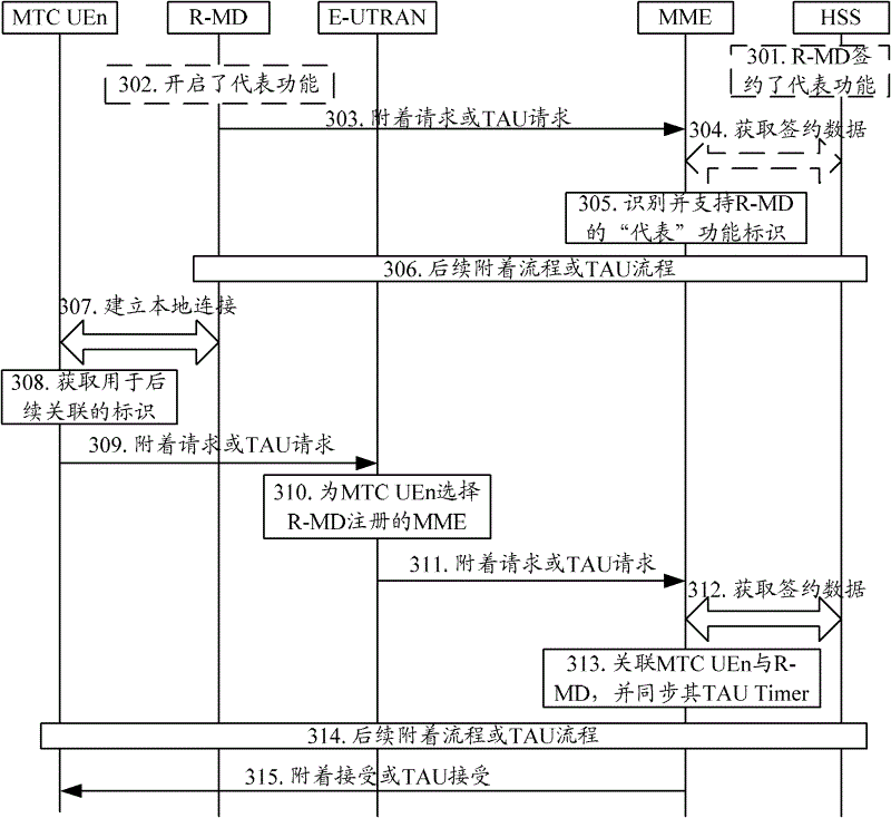
[0109] Embodiment 1: The co-located R-MD and MTC UE are directed to the same MME, and the MME establishes an association relationship between the R-MD and the MTC UE, such as image 3 shown.

[0110] image 3 The flow shown specifically includes the following steps:

[0111] Step 301: The representative function of R-MD is optionally subscribed in HSS as subscription data;

[0112] Step 302: R-MD may be designed to have multiple functions other than the representative function, then R-MD needs to enable the representative function;

[0113] Step 303: After the R-MD activates the representative function, if the R-MD is not attached to the network, it will send an attach request message to the MME; if the R-MD has attached to the network, it will send a TAU request message to the MME, which carries the activation representative identification of the function;

[0114] Step 304: If the representative function of the R-MD needs to be subscribed, the MME checks the subscription...

Embodiment 2

[0127] Embodiment 2: The co-located R-MD and MTC UE are directed to the same MME, and the MME establishes an association relationship between the R-MD and the MTC UE, such as Figure 4 shown.

[0128] Figure 4 The flow shown specifically includes the following steps:

[0129] Step 401: Establish a local connection between R-MD and the MTC UE that will be co-located with it. At this time, if the identifier used for subsequent association is the temporary identity identifier of R-MD, that is: GUTI in LTE network, GUTI in 3G If the network is P-TMSI, when the R-MD is not attached or the R-MD has not obtained the latest temporary identity, the R-MD will not issue the temporary identity to the MTC UE, and the MTC UE will only receive the temporary identity from the R-MD. After the identification of the MD, the subsequent steps 410 to 416 are initiated; optionally, the identification of the MTC UE for subsequent association is sent to the R-MD;

[0130] Step 402: The representat...

Embodiment 3

[0146] Embodiment 3: R-MD replaces MTC UE to perform subsequent periodic tracking area update procedures, such as Figure 5 shown.

[0147] Figure 5 The flow shown specifically includes the following steps:

[0148] Step 501: The R-MD and the MTC UE move together, and the R-MD detects that a periodic TAU process is required or detects that a tracking area (TA) not in the tracking area identifier (TAI) list is performed;

[0149] Step 502: R-MD initiates a TAU request message to MME;

[0150] Step 503: After receiving the TAU request message from the R-MD, the MME locally updates the context of the R-MD and its associated MTC UE;

[0151] Step 504: R-MD performs subsequent periodic TAU process;

[0152] Step 505: MME sends a TAU acceptance message to R-MD, if the TAU process is caused by TA change, MME issues a new TAI list;

[0153] Step 506: The R-MD notifies the MTC UE of whether the TAU process is successful through the local connection, and the MTC UE performs subseq...


PUM


Abstract

The invention discloses a signaling optimization method and a signaling optimization system for MTC devices set together. The following steps are performed in both the method and the system: an R-MD and a MTC UE which are set together are directed to a same mobile management unit, and an association relationship between the R-MD and the MTC UE is established; subsequent mobility management flow is performed by the R-MD instead of the MTC UE based on the association relationship; and the R-MD is used to represent the MTC UE, and is a terminal similar to the MTC UE. For the MTC UE set together, the method and the system provided in the invention can realize optimization for signaling associated with mobility management according to the characteristics of the MTC UE, reduce the mobility management signaling, signaling peak value and electrical loss of the terminals, at the same time when the MTC devices can communicate with respective MTC servers independently.

Description

technical field [0001] The present invention relates to the communication field, in particular to a signaling optimization method and system for co-locating Machine Type Communication (Machine Type Communication, MTC) equipment. Background technique [0002] With the sudden emergence of World Interoperability for Microwave Access (WiMax) technology, the third-generation mobile communication system must improve its network performance and reduce network construction and operation costs in order to maintain its competitiveness in the field of mobile communication . Therefore, the standardization working group of the 3rd Generation Partnership Project (3GPP, 3rd Generation Partnership Project) is currently working on the research of PS Core (Packet Switch Core, packet switching core network) and UTRAN (Universal Mobile Telecommunication System Radio Access Network, global Evolution of mobile communication system wireless access network). The research topic is called System Ar...

Claims


Application Information

Patent Timeline
Patent Type & Authority Applications(China)
IPC IPC(8): H04W4/20H04W8/02H04W24/02H04W4/70
CPCH04W8/02H04W4/005H04W4/20H04W24/02H04W4/70
Inventor 李勉吴昊梁爽卢飞
Owner ZTE CORP
Why Eureka
Try Eureka