Draw-bar box having traveling supporting mechanism

A technology of support mechanism and trolley case, which is applied in the direction of luggage, travel goods, applications, etc., can solve the problems that the trolley case cannot be self-balanced, the labor intensity is high, and the loss of happiness is achieved, and the performance is reliable, the labor intensity is reduced, and the happiness is improved. Effect

Inactive Publication Date: 2012-08-08
KUNMING UNIV
View PDF5 Cites 6 Cited by
  • Summary
  • Abstract
  • Description
  • Claims
  • Application Information

AI Technical Summary

Problems solved by technology

[0002] During business trips or travel, people need to go to and from the station, transfer vehicles during the journey, enter and exit the airport, stay in a hotel and shop, etc. People need to walk for a certain distance. Balance, people need to lift the lever with their hands and pull it to walk, the labor intensity is high, so that the pleasant travel may lose happiness due to fatigue

Method used


Image

  • Draw-bar box having traveling supporting mechanism
  • Draw-bar box having traveling supporting mechanism
  • Draw-bar box having traveling supporting mechanism

Examples


Embodiment Construction

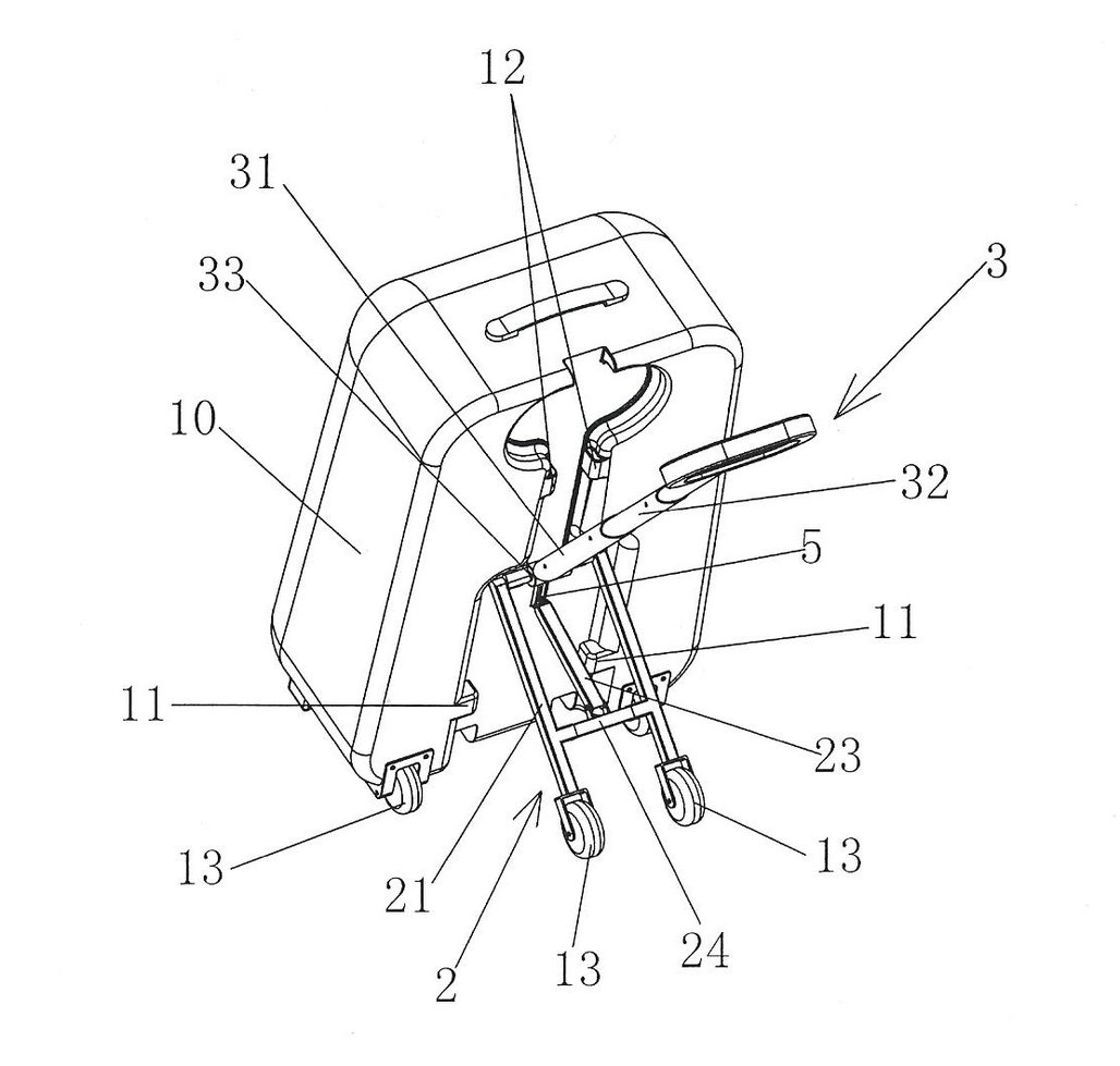
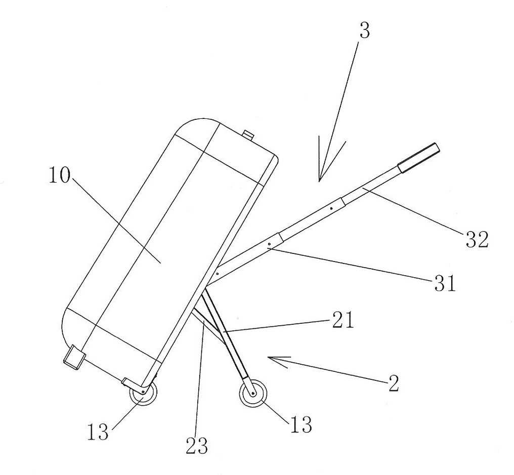
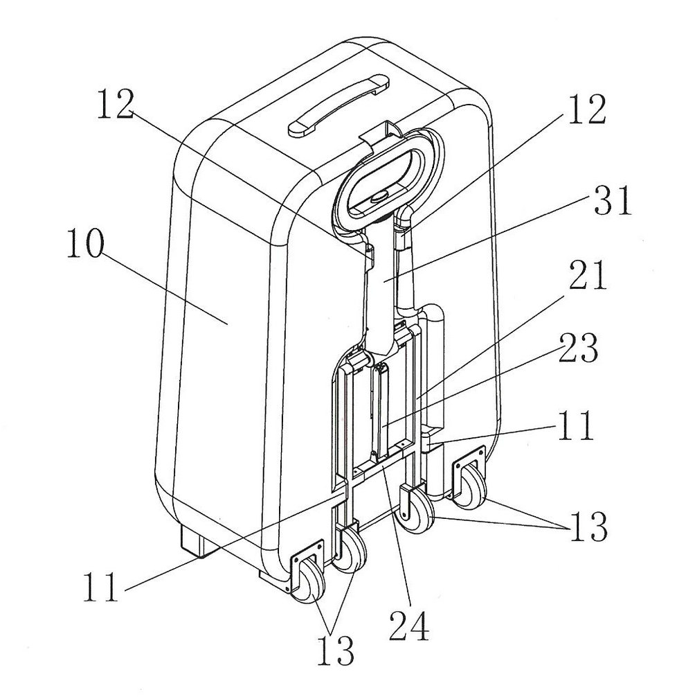
[0016] see figure 1 , figure 2 and image 3 As shown, this embodiment is composed of a box body 10, a freely rotating pull rod 3, a swing rod slider mechanism 2 and a non-return mechanism 5. The two feet of the box body 10 are equipped with casters 13; the free rotating pull rod 3 is composed of basic The pull rod 31 and the telescopic pull rod 32 are composed, the telescopic pull rod 32 is sleeved in the basic pull rod 31, and the basic pull rod 31 and the swing rod 21 share a stepped shaft 33 supported by a double bearing seat fixed on the box body; the swing rod slider mechanism 2 is composed of a pendulum rod 21, a connecting rod 23, a slider 51 and a box body 10, the beam 24 is connected between the two pendulum rods 21, and the top ends of the two pendulum rods 21 are fixedly connected with the two ends of the ladder shaft 33. , the lower end of the connecting rod 23 is hinged with the beam 24, the upper end of the connecting rod 23 is pivotally connected to the slide...


PUM


Abstract

The invention discloses a draw-bar box having a traveling supporting mechanism, which consists of a box body, a free rotation draw bar, a swinging rod slide block mechanism and a stopping mechanism, wherein two bottom feet of the box body are respectively provided with a trundle wheel; the free rotation draw bar consists of basic draw bars and retractable draw bars, each retractable draw bar is nested inside one basic draw bar, and each basic draw bar and one swinging rod share one staircase shaft which is fixedly connected onto the box body and is supported by a double-shaft bearing seat; the swinging rod slide block mechanism consists of two swinging rods, a connecting rod, a slide block and a box body, wherein a crossbeam is arranged between the two swinging rods, the top end of each swinging rod is fixedly and respectively connected with two ends of the staircase shaft, the lower end of the connecting rod is hinged with the crossbeam, and the upper end of the connecting rod is pivoted with the slide block of the stopping mechanism; the draw-bar ox is set at a standing state, the swinging rods are rotated until the slide block slides to a lower stop point of the slide block, the box body is rotated until four trundle wheels are landed, and the draw-bar box can be pulled to move by rotating and pulling out the draw bar; and the draw-bar box is set at the standing state, a pallet is slightly pressed towards the inner side direction of the box body, the swinging rods are rotated until the slide block slides to an upper stop point of a slide-way, the swinging rods are respectively clamped by a clamping block, the free rotation draw bar is withdrawn and rotated to be clamped by the clamping block, and the box body stays at a laying state.

Description

technical field [0001] The invention relates to a trolley case, in particular to a trolley case with a walking support mechanism. Background technique [0002] During business trips or travel, people need to travel to and from the station, transfer vehicles between journeys, enter and leave the airport, stay in hotels and shopping, etc. People need to walk for a certain distance. Balance requires people to lift the rod and pull it to walk, which is labor-intensive, so that a pleasant trip may lose happiness due to exhaustion. SUMMARY OF THE INVENTION [0003] The purpose of the present invention is to provide a trolley case with a walking support mechanism, the trolley case can balance itself in the walking state, people do not need to lift the trolley by hand, and the freely rotatable trolley can meet the needs of people of different heights, only need to use By pulling the lever by hand, the trolley case can walk on a relatively flat road or floor such as a square brick...

Claims


Application Information

Patent Timeline
IPC IPC(8): A45C5/04A45C5/14
Inventor 于向军徐志强刘景扬孙艳萍胡季
Owner KUNMING UNIV
Why Eureka
Try Eureka