Combination structure of mechanical arm sliding table and guide beam

A combined structure and manipulator technology, applied in the field of manipulators, can solve the problems of environmental impact on the work site, increase the labor intensity of workers, and increase the cost of equipment use, so as to reduce the maintenance intensity and use cost, improve the effect of smooth motion, and reduce maintenance. cost effect

Active Publication Date: 2012-08-08
CHANGSHU HUIYI MECHANICAL&ELECTRICAL CO LTD
View PDF5 Cites 1 Cited by
  • Summary
  • Abstract
  • Description
  • Claims
  • Application Information

AI Technical Summary

Problems solved by technology

[0006] The above-mentioned structure has the following disadvantages: First, it is difficult for the slide table 2 to ensure a lasting smooth motion effect, because during the reciprocating motion of the slide table 2, the first and second The two guide rail sliders 21,22 rub against the first and second guide rails 11,12, so after a period of use, due to the first and second guide rail sliders 21,22 and / or the first and second guide rails 11,12 If there is friction, the stability of the motion of the slide table 2 will be affected, and eventually the accuracy of the action of the manipulator will be affected. 1. The contact surface between the second guide rails 11 and 12 is large, so the kinetic energy consumed is just increased, which is not conducive to saving the electric energy of the drive mechanism 4, and is incompatible with the energy-saving and energy-saving economic spirit advocated by the whole society at present; third, Affect the working efficiency of the mechanism hand, because when the first and second guide rail sliders 21, 22 and / or the first and second guide rails 11 and 12 are worn out, they need to be replaced in time, otherwise it will affect the aforementioned actions (movements) of the slide table 2 ) stability, while the replacement of the first and second guide rail sliders 21, 22 and the first and second guide rails 11 and 12 needs to be carried out in a shutdown state, and the first and second guide rail sliders 21, 22 and the first and second guide rail sliders 21, 22 and the first One, the use cost of the second guide rail 11,12 can increase the use cost of the equipment and increase the labor intensity of the worker; Its four, produce noise pollution, because the first and second guide rail slide blocks 21,22 are on the first and second guide rail When moving on 11 and 12, it is easy to produce harsh noise, which will affect the environment of the work site

Method used


Image

  • Combination structure of mechanical arm sliding table and guide beam
  • Combination structure of mechanical arm sliding table and guide beam
  • Combination structure of mechanical arm sliding table and guide beam

Examples


Embodiment

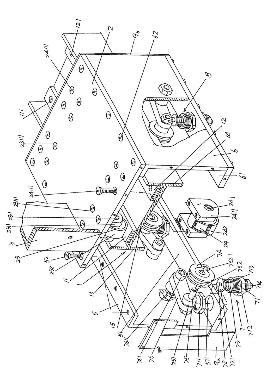
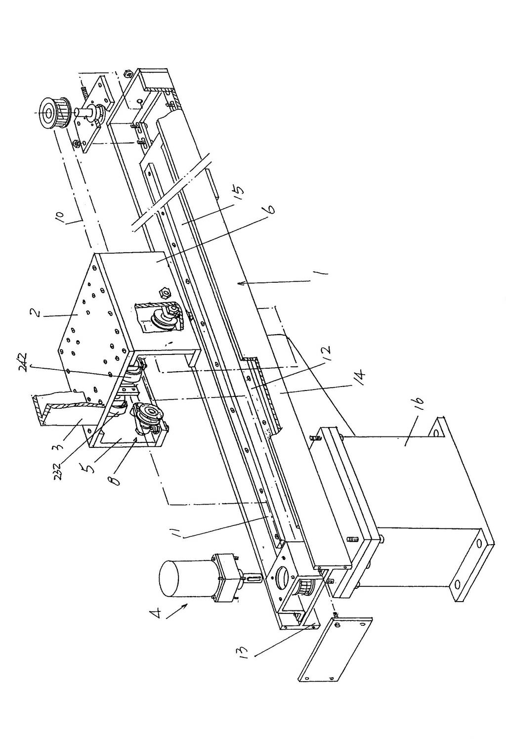
[0026] Please see figure 1 , a guide beam 1 is provided, and the guide beam 1 is composed of first and second side walls 13, 14 and a bottom wall 15 between the first and second side walls 13, 14 to form an H-shaped cross-sectional shape The shape, that is, the guide beam 1 adopts H-shaped steel. The side of the guide beam 1 facing upward in the state of use, more specifically, the side of the bottom wall 15 facing the surface of the slide table 2 to be described below is fixed with a first guide rail 11 with a first screw 111, and the other side is fixed with a first screw 111. The second screw 121 fixes a second guide rail 12, and the first and second guide rails 11, 12 are parallel to each other.

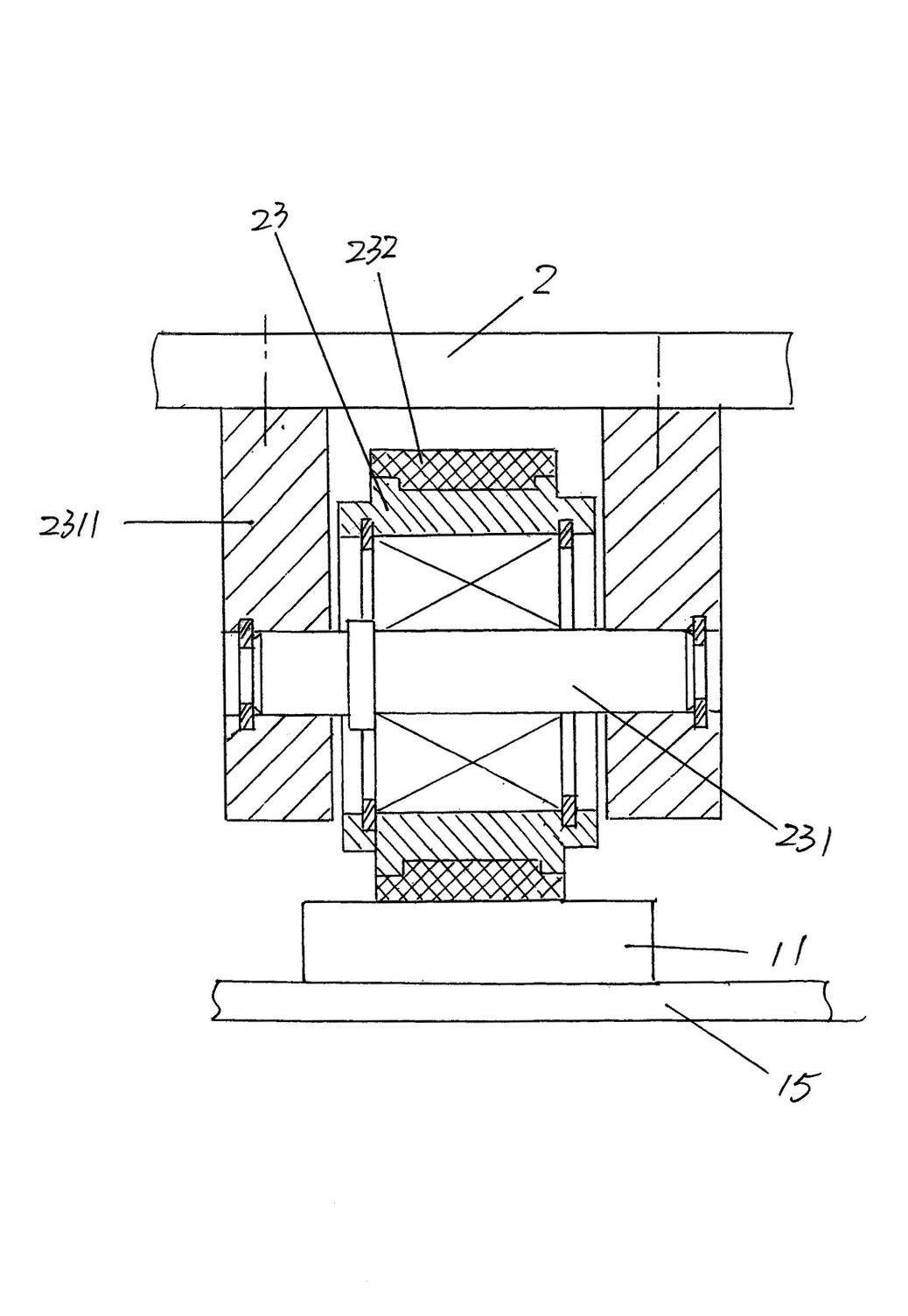
[0027] A slide table 2 that can be either rectangular parallelepiped or square and flat is matched with the aforementioned guide beam 2, specifically: on the side of the slide table 2 facing the guide beam 1 and on the side corresponding to the first guide rail 11 A pair of...


PUM


Abstract

The invention relates to a combination structure of a mechanical arm sliding table and a guide beam, belonging to the technical field of mechanical arms. The combination structure comprises a sliding table and a guide beam with a first guide rail and a second guide rail. The combination structure is characterized in that the guide beam comprises a first side wall, a second side wall and a bottom wall; one side facing towards the bottom wall of the sliding table is provided with at least one pair of first rollers, and a first suspension sleeve is sleeved on each first roller; the other side facing towards the bottom wall of the sliding table is provided with at least one pair of second rollers, and a second suspension sleeve is sleeved on each second roller; the side facing towards the first side wall of the sliding table is stretched out of the first side wall, and a first side plate is fixed at the side; the side facing towards the second side wall of the sliding table is stretched into the second side wall, and a second side plate is fixed at the side; a first adjustment device is arranged on a first side plate bottom wall of the first side plate; and a second adjustment device is arranged on a second side plate bottom wall of the first side plate. The combination structure has the advantages of improving the steady movement effect of the sliding table, reducing the frictional force, saving energy, lightening the maintenance strength, reducing the use cost, reducing the stop probability of the mechanical arm, lowering the noise, reducing the maintenance cost and saving sources.

Description

technical field [0001] The invention belongs to the technical field of manipulators, and in particular relates to a combined structure of a manipulator slide table and a guide beam. Background technique [0002] The concept of a manipulator is well known, and it has the function of imitating human hands and arms to complete certain actions. It is an automatic operating device used to grab, carry objects or operate tools according to a fixed program. It can replace human heavy labor. In order to realize the mechanization and automation of production. In particular: because it can protect personal safety in harmful operating environments, it is widely used in fields such as machinery manufacturing, metallurgy, electronics, light industry and even atomic energy. [0003] The manipulator is mainly composed of a hand (the industry is accustomed to call it a claw) and a motion mechanism. The hand is a part used to grasp the workpiece (or tool), and has various structural forms a...

Claims


Application Information

Patent Timeline
IPC IPC(8): B25J5/02
Inventor 朱建惠
Owner CHANGSHU HUIYI MECHANICAL&ELECTRICAL CO LTD
Why Eureka
Try Eureka