
Lighting device having electric discharge lamp which has electric discharge vessel capable of forming flat screw member

A technology for lighting devices and discharge vessels, applied to lighting devices, fixed lighting devices, components of lighting devices, etc., can solve the problems of position tolerance, difficulty, unfavorable height of lighting device structure, etc., to prevent damage and prevent electrical contact Effect

Inactive Publication Date: 2012-08-08
OSRAM GMBH
View PDF0 Cites 0 Cited by
  • Summary
  • Abstract
  • Description
  • Claims
  • Application Information

AI Technical Summary

Problems solved by technology

As a result, the electrical contact with the driver is limited and thus also disadvantageous with regard to the overall height of the lighting device.
In particular, however, the realization of the base-holder system is only completely specific and thus restricts the conceptual design of the lighting device.
This is because the pins have to be located above the lampholder contacts in order to make the contact, which is made difficult by the positional tolerances of the lamp ends which always occur in such lamps and has to be compensated

Method used


Image

  • Lighting device having electric discharge lamp which has electric discharge vessel capable of forming flat screw member
  • Lighting device having electric discharge lamp which has electric discharge vessel capable of forming flat screw member
  • Lighting device having electric discharge lamp which has electric discharge vessel capable of forming flat screw member

Examples


Embodiment Construction

[0027] Identical or identically acting elements are provided with the same reference symbols in the figures.

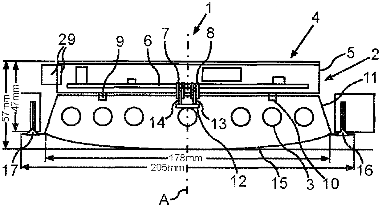
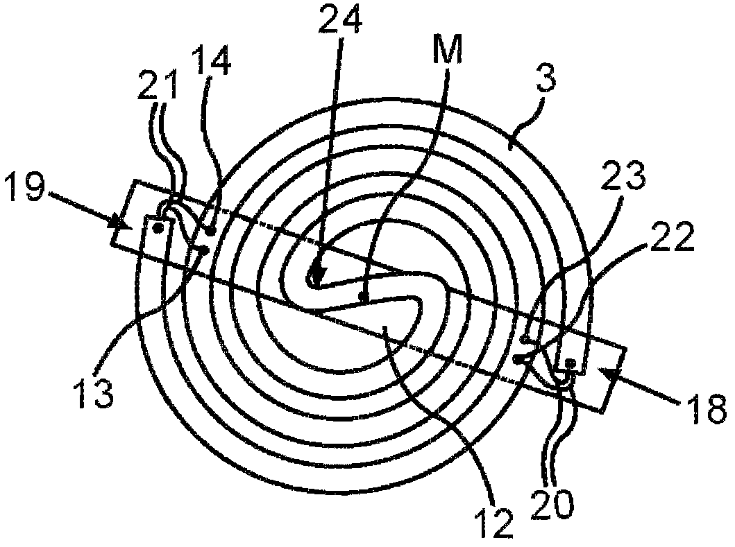
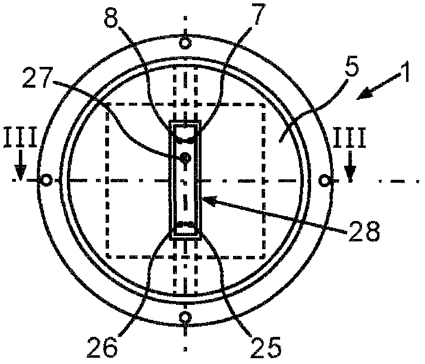
[0028] exist figure 1 A schematic sectional view of a lighting device 1 with an integrated discharge lamp 2 is shown in . The discharge lamp 2 comprises a discharge vessel 3 which is formed as a tubular and double-wound tube in two planes, said tube having feed leads protruding at its ends; The contact carrier 12 on the part has contact pins 13, 14, 22 and 23 fixed thereon. The discharge vessel 3 extending in a plane is thus formed as a flat spiral. The discharge vessel 2 is therefore also denoted as a flat lamp in the context of the present invention. Furthermore, an electronic driver 4 is arranged downstream of the discharge vessel 3 in the direction of the longitudinal axis A of the lighting device 1 . The driver 4 embodied as an electronic ballast comprises a housing 5 . A printed circuit board or circuit carrier 6 is arranged in the housing. A plurality of ...


PUM


Abstract

The invention refers to a lighting device having an electric discharge lamp (2) which has an electric discharge vessel capable of changing into a flat screw member. The lighting device is provided with an electric driver (4) designed to operate the electric discharge lamp (2) and contact with an electric discharge vessel (3) by means of electric contacts, wherein a plate-like contact carrier (12) is made of electrical insulative materials and connected with the electric discharge vessel(3), wherein the contact carrier (12) at least extends in sections over the discharge vessel (3). Electric contacts (13, 14,22,23) of the vessel (3) are arranged at the contact carrier (12) and extend in a direction of the driver (4) with end regions (18,19) of the electric discharge vessel (3).

Description

technical field [0001] The invention relates to a lighting device with a discharge lamp having a discharge vessel formed as a flat spiral. The lighting device includes an electronic driver, the device is provided for operating the discharge vessel and is connected to the discharge vessel by means of electrical contacts. Background technique [0002] Discharge lamps are known which have a helically wound discharge vessel extending in a plane. In such lamps, however, due to the design, it was necessary to arrange electrical contacts at the ends of the discharge vessel, so far it was only possible to arrange electrical contacts at these ends. The electrical contacts then extend out of the end to a certain extent along the course of the flat spiral and thus also extend in the plane of the flat spiral. As a result, the electrical contact with the driver is limited and thus also disadvantageous with regard to the overall height of the lighting device. In particular, however, th...

Claims


Application Information

Patent Timeline
Patent Type & Authority Applications(China)
IPC IPC(8): H01J61/56F21V23/06
CPCF21Y2103/02H01J61/307F21V23/02F21S8/02F21Y2103/30
Inventor 托马斯·诺尔
Owner OSRAM GMBH
Learn More